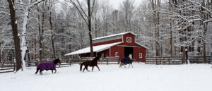
Hopping in the “Wayback Machine” to November 1989. My company, M & W Building Supply, in Canby, Oregon, had provided an 80’ x 204’ x 16’ post-frame riding arena to Percy Freeman (inventor of Freeman Bailer, amongst other things) in Molalla.
Roughly a month prior, we had delivered a fairly similar building package to a builder in Eastern Oregon, who had it collapse during construction due to excessive winds. Percy’s building was being erected by our sister company, Jim Betonte’s Farmland Structures. Jim’s crew chief, Brad Moore, stopped by our office Wednesday afternoon before Thanksgiving to let us know the building was all framed up.
As a high wind warning was predicted for Thanksgiving Day, I related to Brad about our recent Eastern Oregon experience. Brad assured us everything was braced and braced again.
Thanksgiving Day winds were even more potent than expected – reaching upwards of 80 miles per hour in Molalla. Winds were so strong 2x6s were picked off tops of units in our lumberyard!
Coming back after a four-day weekend of family, food and football, we were greeted by news of Percy’s building: it was flattened.
Upon examination, we found our culprit – a full sawn 6×10 sidewall column had an impossible-to-foresee timber break and had failed, sucking the balance of building down with it. We had a big hole dug behind this building site and pushed what remained (as it was all reduced to firewood) into it.
While this short and sad story was about a building under construction, it does show what can happen during wind events and solutions exist that could have avoided this tragedy.
Most of us watch some sort of television news and see videos of buildings ripped to shreds by extreme wind events, whether tornados or hurricanes.

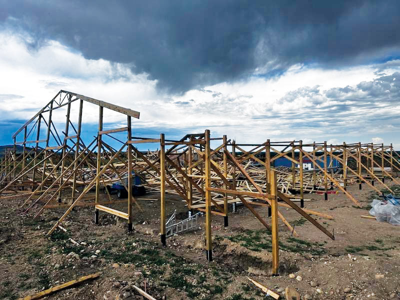
Significant damage caused by high winds.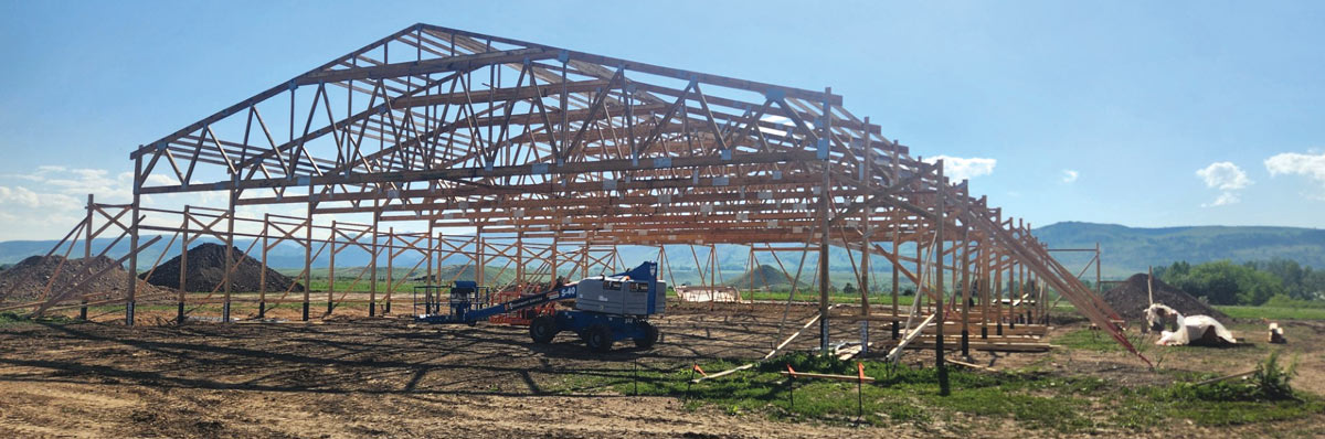
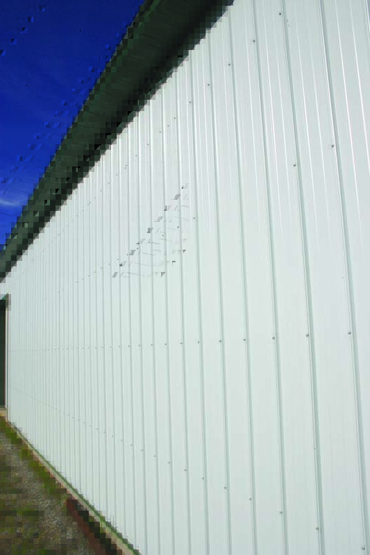
Framing system intact. All images courtesy of Hansen Pole Buildings
Tornados, They Blow
As an example, between 1989 and 2013 Oklahoma alone experienced 1,597 tornadoes producing roughly $30 billion in insured losses. If tornadoes continue at this rate, this state will experience more than $100 billion in insured losses over the next 50 years. Other states, including Mississippi, Alabama, and Missouri, face a similar plight. Engineers indicate relatively simple and inexpensive enhancements to building codes may reduce insured losses by 30% or more and economists indicate these measures “easily pass a benefit cost test” in multiple states (Simmons, Kovacs, & Smith, 2018).
Even for most intense tornadoes, most structural damage occurs at points along a tornado’s path where the tornado was rated an EF2 or lower (Ramsdell & Rishel, 2007). For example, a post-event National Weather Service damage survey to evaluate Joplin, Missouri’s May 22, 2011 EF5 tornado—causing $2.8 billion in damage—determined 6,149 (86%) of 7,191 structures damaged were exposed to an EF2 or lower tornado (Marshall, Davis, & Runnels, 2012). Similarly, 80% of structures damaged by this third-most costly tornado in U.S. history (EF5 tornado striking Moore, Oklahoma, on May 20, 2013, and causing $2 billion in damage) occurred when tornado was rated an EF2 or lower (Burgess et al., 2014). Thus, a substantial percentage of damage caused by tornadoes comes from less-intense tornadoes producing wind speeds ranging from 65 to 135 mph.
Understanding Winds
Author’s disclaimer: I went to school to be an architect, I am not a Registered Professional Engineer. Below is meant to be a broad overview, not necessarily all inclusive. For actual structural design, services of a Registered Professional Engineer should be engaged.
IBC (International Building Code) provides us with basic design wind speeds in Section 1609.3. Footnote 5 under each of these pretty maps, gives a probability for these design wind speeds to be exceeded over next 50 years. For Risk Category I 15%, II (most buildings) 7%. This is not a huge confidence builder!
Besides basic design wind speeds, exists a highly ignored, but extremely important factor—exposure factor. IBC Section 1609.4.3 gives definitions, but suffice to say, while most buildings should be designed for Exposure C, very few are—instead opting for a lesser Exposure B. For practical purposes, at an identical wind speed, Exposure C produces roughly 20% more force than Exposure B!
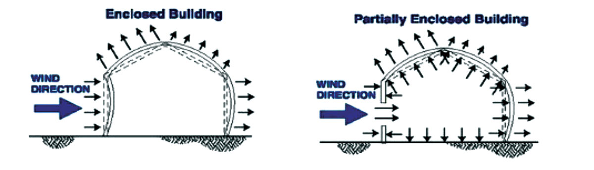
Building Enclosure allows us to consider pressure differences between building inside and outside. Most critical is usually enclosed (air generally doesn’t come in) and partially enclosed (air flows in, but cannot escape). Think of partially enclosed as blowing up a balloon. Studies indicate wind forces can be 1.5 to 3 times greater in partially enclosed buildings compared to enclosed ones, depending upon specific conditions. Be wary about three-sided buildings, or buildings where doors and windows are not properly wind load rated.
MWFRS vs. C & C
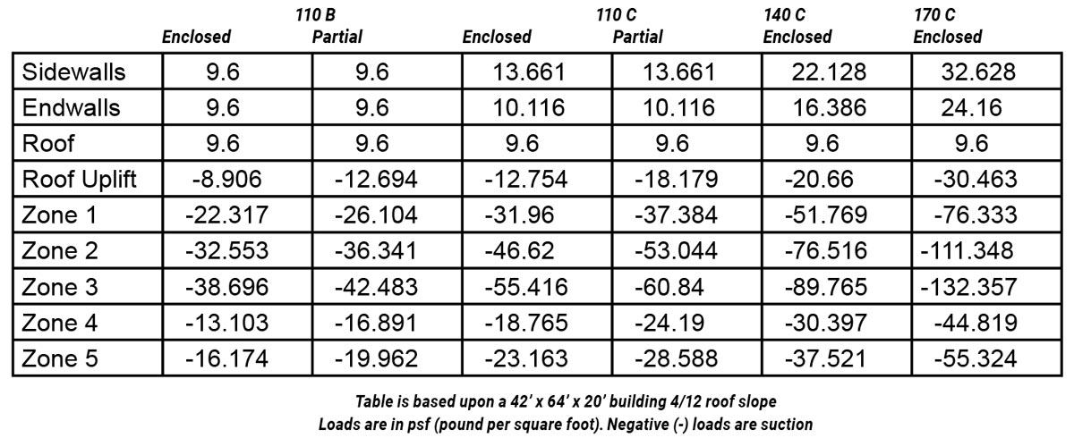
MWFRS (Main Wind Force Resisting System) are your columns and trusses. C & C (Components and Cladding) are girts, purlins, doors, windows, roofing and siding. MWFRS wind design pressures are lower (per square foot) due to larger area expanse, compared to C & C pressures.
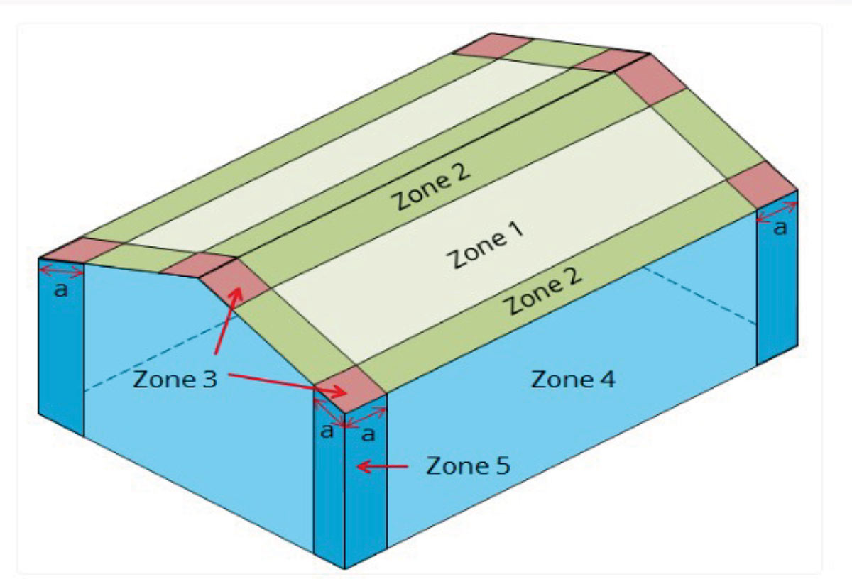
Areas of Discontinuity (Zones 2, 3 and 5 below) have greater wind design pressures. These areas are equal to 10% of least horizontal dimension or 40% of wall height, whichever is smaller, but not less than either 4% of least horizontal dimension or three feet.
How To Do Higher Design Wind Speeds Right
Start by having every post-frame building built to site-specific plans sealed by a Registered Professional Engineer. Engineering is an investment, not an expense. A good engineer will save more in materials efficiency than what they get paid. It can be sold as a benefit to your client: It is an assurance that every component and connection has been reviewed for structural adequacy. Some insurance companies give premium discounts for engineered buildings. Plus, it takes liability away from you. If it is not engineered and fails, some attorney is likely coming looking for you.
What We Did at Hansen Pole Buildings
Remember our timber broken 6×10? We have gone to all true glulaminated columns for roof supports. And, we have taken them up a notch by having them manufactured from 2400msr lumber. These are over 45% stronger than any other readily available post-frame building columns. Glulam columns do not have timber breaks. On our hypothetical 42’ x 64’ x 20’ building, at 140 mph and Exposure C, columns every 16’ are 4 ply 2×6 glulams.
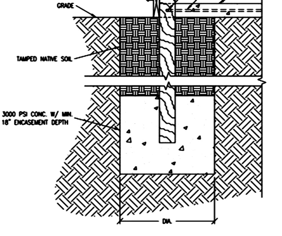
Make provisions for uplift – concrete bottom collars are very effective. (See top diagram next page.)
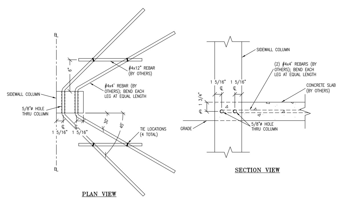
Use rebar hairpins through sidewall columns. This allows for embedment calculations to be in a “constrained” condition, reducing hole depths and/or diameters, as well as helping resist uplift. When detailed properly, it can also reduce required footing diameter by spreading downward loads partially into concrete slabs on grade.
Bookshelf wall girts. A 2×6 externally mounted wall girt has a section modulus (Sm) of 2.0625, rotate it 90 degrees and Sm becomes 7.5625. For resisting deflection I for an external 2×6 is 1.55, bookshelf it and I becomes 20.8 (over 13 times stiffer against wind).
Reduce number of connections. More often than not failures occur due to connections; either they were inadequate or were poorly placed. We gang our roof trusses into pairs and place them into a notch from one side of columns. No truss to carrier to column connections to deal with and with our high strength columns we can place columns every 12 to 16 feet, even with high design wind speeds. I have been designing roof trusses since 1977. Placing trusses face-to-face in pairs significantly reduces amount of required bracing and often results in smaller dimension material for truss chords.
Speaking of connections, old timers will remember nailing on steel roofing and siding. Today, no one would begin to even consider it. Wood-to-wood, structural screws outperform any sort of nail. From 2018 NDS Table 11.3.3 if building with green lumber (over 19% moisture content), nails with a diameter of under ¼” have a 30% reduction in lateral strength and a 75% reduction (no reduction for post-frame ring shank nails) in withdrawal values! This would include driving through a dry 2x member into a solid-sawn pressure preservative treated column.
Attach purlins to trusses with engineered connectors. For ease of assembly, as well as ability to withstand uplift, we use Simpson PFDS saddle hangers.
Do away with attempts at knee bracing and corner diagonal bracing. Knee braces often do more harm than good, especially if roof trusses are not designed to carry loads imposed by these knees. Diagonal bracing becomes problematic, as it is impossible to place enough fasteners in ends of braces to carry other than minimal loads.
Utilize shear strength of your steel roofing and siding. Over 30 years ago, we conducted full scale tests of steel panels to determine shear strength. We found several things: Screws must be in ‘flats’ to be effective; 1” long screws pull out of lumber under minimal loads; #9 or #10 diameter screws created slots around screw shanks as loads are cycled; highest forces are at ends of panels, requiring screws each side of every high rib.
In our instance, engineer Merl Townsend designed what is now Leland’s “Diaphragm screw.” This #12 x 1-1/2” part has a ¼” diameter shank where screw penetrates steel. No pull outs, no slotting.
While most cannot afford to do this sort of testing, there are available resources for engineers to calculate shear strength of panels. As greater values are needed, stitch screws can be added to overlaps, thicker steel can be used, or both.
What about walls with lots of openings? Shearwall trusses can be incorporated to transfer loads from roof to ground.
Remember those high wind pressure Zones #2, 3 and 5? Loads in these areas may be beyond capacity of your steel cladding. If so, there are solutions: Add framing members between typical spacing to reduce spans or use thicker steel in these areas.
Do not neglect wind-load rated doors. Your clients might like balloons for birthday parties, but not so much for their new building.
Our hypothetical building again….for a fully enclosed ‘box’ (no openings) going from 110 B to C added 0.4% to cost; to 140 C 0.6%; to 170 C 1.8%.