By Sean Shields
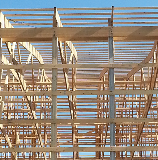
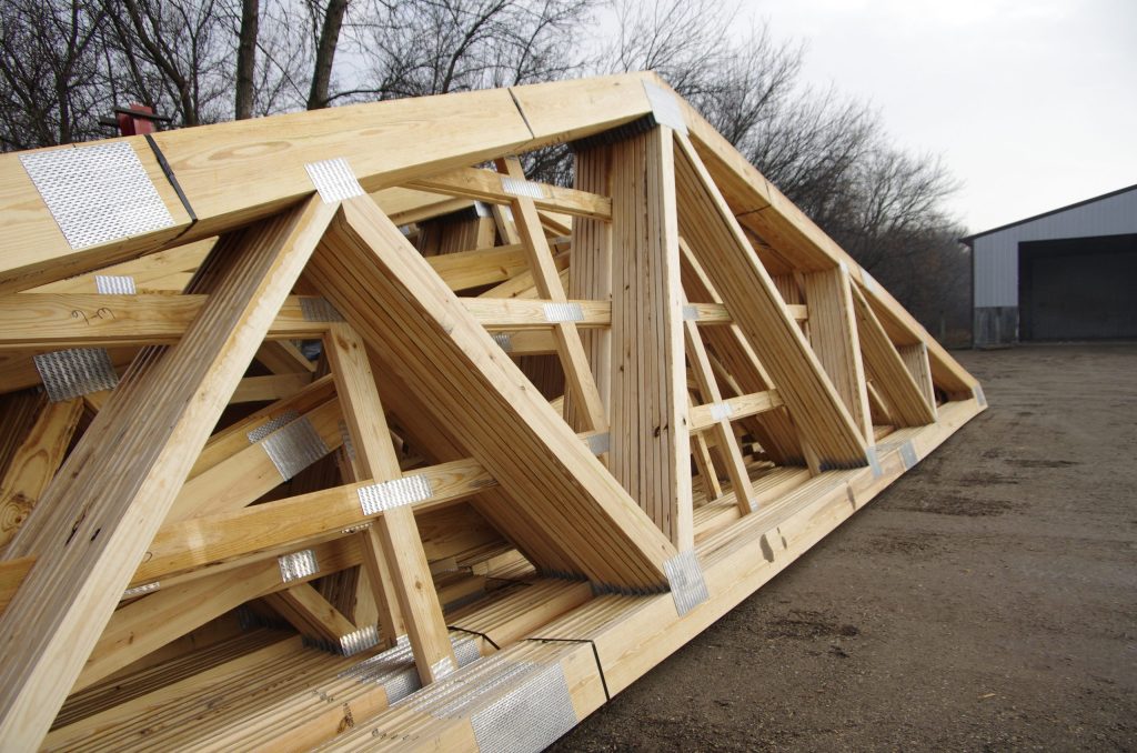
Trusses are incredibly efficient structural framing elements. By using a series of interconnected triangles, trusses transfer significant forces to their heels, allowing for the very large roof spans typically seen in today’s post-frame construction.
When installing trusses, builders and installers should keep in mind that while long-span trusses have superior performance within the plane of the truss, when trusses bend out-of-plane there is the potential trusses can be damaged to the point of needing repair. One area where damage can occur is at the truss joint, and to better understand the impact of potential damage this article will look at the metal connector plate itself.
How the Connector Plate Functions
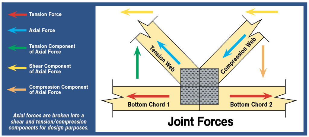
Beyond the triangular construction, the workhorse of every truss is the metal connector plates that hold the various webs and chords together at the joints. At a truss joint, the teeth of a connector plate transfer various forces from one wood web or chord into the plate itself (see the Joint Forces graphic, page 20). Shear and axial forces in the truss plate are then transferred across the joint line, where teeth on one side of the joint transfer the forces into the adjoining wood web or chord. In this way, the truss connector plate acts like a bridge between one wood member and another.
When a component manufacturer designs a truss, they use software to identify the paths each type of load will travel through the truss. The magnitude of the forces being resisted and the span of the truss impacts everything from the quantity and location of webs to the grade of lumber and size of the connector plates. At a basic level, a truss designer works through these variables to arrive at the most efficient configuration at each location of a building.
The Efficiency of the Connector Plate
It’s hard to appreciate how sophisticated today’s metal connector plates are just by looking at them, particularly when they are already embedded in a truss on the jobsite. Without getting too deep into engineering principles and complex formulas, let’s look at a simple example to understand what a connector plate can do. Take a simple splice joint between two bottom chord SPF #2 wood members. A 3″x6″ plate embedded on both sides of that truss joint would provide 4,264 pounds of lateral resistance (i.e., holding the two members together as the forces in the truss act to pull them apart). A typical 10d gun nail in SPF #2 has 94.3 pounds of lateral resistance. This means it would take 46 nails on each side of the splice to resist the same force as a 3″x6″ plate. The next time you look at the large plates on your long-span trusses, try to imagine how many nails you would have to use to replace them!
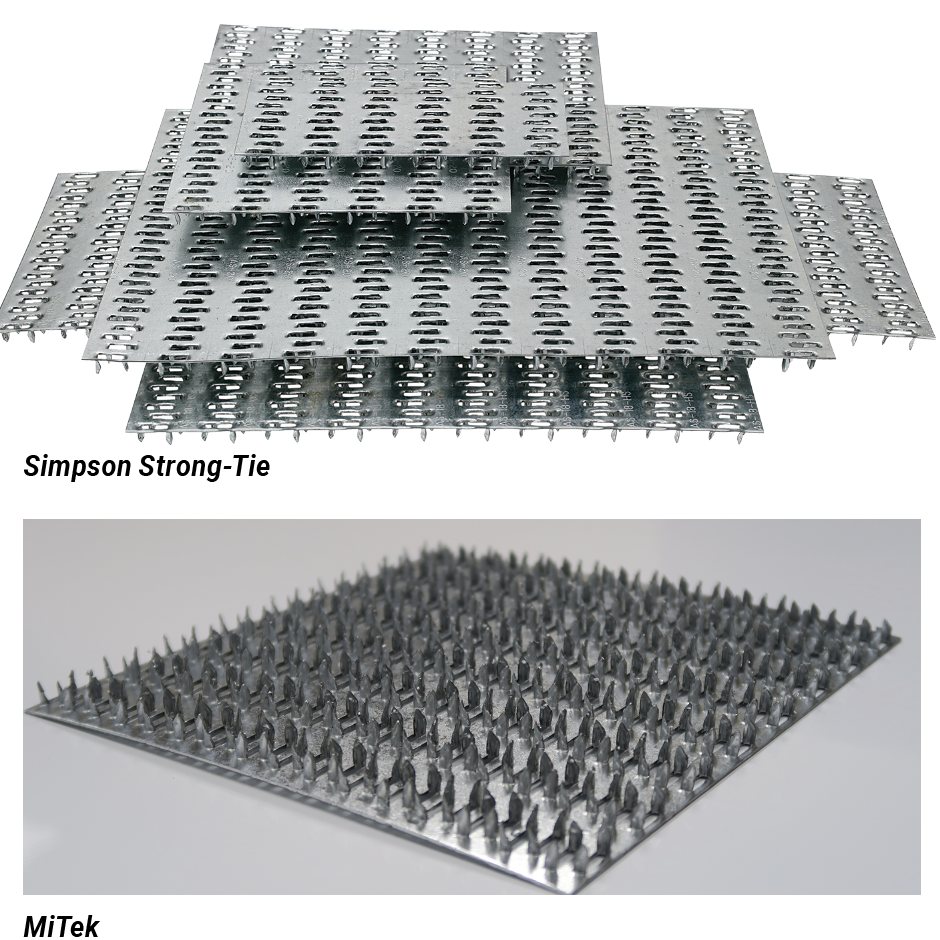
There are currently four plate manufacturers in the United States:
-MiTek
-Alpine, an ITW Company
-Eagle Metal Products
-Simpson Strong-Tie
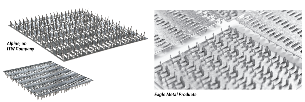
At first glance, every connector plate may look the same. However, each of these manufacturers has developed their own product. While the mechanical properties of the sheet steel used are similar, once that material is stamped into a truss plate, it has its own unique strength properties.
Each of the four plate manufacturers have developed proprietary truss design software that incorporates their plates’ performance characteristics based on years and years of testing and evaluation.
A Finely Tuned Manufacturing Process
The metal connector plate is truly a modern marvel, and the proprietary design software is an incredibly robust tool that allows today’s component manufacturer to apply complex engineering principles to lay out efficient truss configurations every time. Yet, it’s also important for builders and installers to know that the truss manufacturing process provides the precision necessary to ensure every truss performs as intended.
Today’s truss manufacturer uses computer-guided saws to ensure every cut is at exactly the right angle, and every chord and web member is exactly the correct length. Assembly on the modern gantry table comes with computer-aided joint configurations and laser-guided plate placement. This approach ensures each truss joint has sufficient wood fiber to embed the connector plate teeth into.
One key differentiator between the plates of the four plate manufacturers is the teeth orientation and how the teeth are rotated or aligned (see the photos on the final page as examples). After a truss is laid out on the assembly table, the plates are embedded using rollers or hydraulic presses. These approaches ensure the teeth of the connector plate have the proper connection to the fiber of the wood webs and chords at every joint.
Inspecting Potential Field Damage
During truss installation, it is not uncommon for long span trusses to bend out of plane. Long span trusses are heavy, and as we’ve covered in previous articles, they are not designed to resist out-of-plane bending. It is up to the installer to follow the best practices, like those found in the Building Component Safety Information (BSCI) handbook to minimize it in the field.
If sudden or excessive out-of-plane bending does occur, it is recommended that installers inspect the joints of the truss. In particular, installers should look for damage to each truss plate in the form of rippling on the surface or bending at the edges. It is also possible that bending at the joint may cause the plate to back out of the wood. The ANSI/TPI 1 Standard requires an “embedment gap,” the space between the underside of the plate and the wood member, be 1/32″ or less. For reference, this is typically the thickness of a credit card. Again, the manufacturing process ensures the teeth of connector plates are properly embedded into the wood fiber. Using a hammer in the field to try to re-embed truss plates is strongly discouraged.
Damage or tearing of the wood fiber by the connector plate teeth around the truss joint is also possible when a truss bends too far out of plane. Torn wood fiber can potentially weaken the strength of a joint. If plate damage, plate pull out, or wood fiber damage is observed, the recommended course of action is to contact the component manufacturer immediately so they can advise on a potential repair.
It should also be noted that installing proper temporary bracing during erection, and permanent restraint and bracing over the life of the building, is also essential for keeping the trusses from bending out of plane. Similar damage to the plates and wood fiber around the joints can occur over the life of the building if the restraint and bracing guidance recommended by the component manufacturer and BCSI is not followed.
Addressing Corrosive Environments
Metal connector plates used in wood trusses are typically fabricated from hot-dip galvanized steel meeting the requirements of ASTM A653/A653M, with a coating that meets or exceeds the designation G60. The zinc coating protects the steel base metal by providing, in essence, a sacrificial layer that corrodes at a rate over 50 times slower than uncoated steel. For most wood truss applications, the G60 coating provides more than adequate protection against corrosion.
This is particularly important to consider when it comes to post-frame buildings because these buildings can be used for certain agricultural purposes, for salt, or bulk fertilizer storage. In these environments, additional corrosion protection may need to be applied to the connector plates. One common method is using connector plates with a thicker zinc coating, either a G185 coating or plates that are hot dip galvanized per ASTM A153, after original plate manufacturing. To pursue this option, the component manufacturer would need to be advised of this preference prior to truss design and manufacturing.
In addition to the post-plate-manufacture hot-dip galvanizing, the ANSI/TPI 1 Standard allows for field-applied epoxies and coal tar epoxies meeting the SSPC Technology Guide No. 19 as coatings that provide increased corrosion protection. When either is used, the surface of the connector plates must be cleaned, and the coatings must be applied in accordance with the SSPC guidance. In any case, it is the responsibility of the building owner to ensure this additional corrosion protection is applied in order to avoid rust build up on the connector plates, which may negatively impact the long term performance of the plate and the corresponding truss. FBN
Sean Shields is Director of Communications for the Structural Building Components Association, better known as the SBCA (www.sbcacomponents.com), and has authored over a hundred articles focused on structural framing and off-site construction since 2004.