
Avoid the Deserted Island
By Sean Shields, Structural Building Components Association
The image of being alone on a deserted island is regularly used to convey a sense of vulnerability. That scenario is meant to remind us that without our normal support structure for food, water, and companionship, a bad outcome is likely in our future.
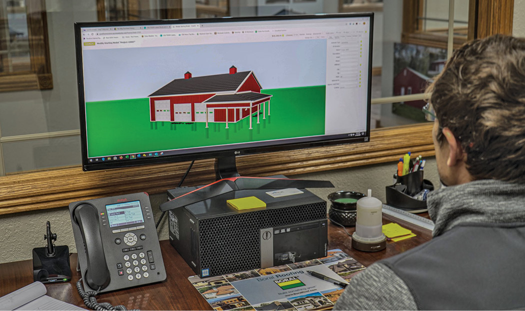
Post-frame construction can often employ a roof truss system where the individual trusses are spaced greater than 2’ on center (2’ o.c.) and the trusses themselves are greater than 60’ in length. During installation, then, each roof truss is on the equivalent of a deserted island. Each truss is incredibly narrow in relation to its depth and span, and as discussed often in the previous articles in this series, an individual long-span truss is susceptible to lateral bending that will cause the truss to twist and buckle.

When spaced more than 2’ o.c., an individual long-span truss simply does not have the support structure it needs to perform as designed, and if left on that deserted island the likelihood of a bad outcome increases. This article will briefly look at the industry-developed best practices an installer should consider using to “rescue” each truss from its island during the erection process. This guidance can be found in greater detail in BCSI-B10, “Post Frame truss Installation, Restraint & Bracing.”
BCSI-B10 Summary Sheet – Post-Frame Truss Installation, Restraint & Bracing
The BCSI-B10 provides guidelines for the proper handling, installing, restraining and bracing of flat bottom chord trusses in engineered post-frame building system applications where trusses are spaced more than two feet on center and the trusses are up to 81 feet in length.
Check All Your Boxes
Before installing the first roof truss in the system, the most important step is progressing through a checklist to verify the supporting foundation and walls the trusses will be installed upon is correct. Some of the key questions to ask are:

• Are all the load bearing supports (e.g. walls, columns, headers, beams, posts, etc.) plumb and properly braced?
• Are all bearing supports accurately installed at the locations shown on the building’s construction documents?
• Are the tops of all bearing supports at the correct elevation; are they straight along their length and parallel where designed?
• Have the appropriate ground bracing techniques for the first truss been determined?
Close attention to these details on every project eliminates potential contributing factors to many truss collapse outcomes. An uneven or improperly constructed bearing surface leads to uneven truss installations that can cause failure of an individual truss or the roof truss system. Further, attempting to fix any issue with the bearing surface once installation begins leads to significant project delays at best, and at worst, eventual structural failure.
Brace Your Walls
After the bearing surface of the trusses is determined to be correct per the building’s construction documents, it is vital to brace the walls prior to roof truss installation to resist the loads being applied by the trusses. The last article in this series focused on ground bracing best practices to consider when installing the first set of trusses, and those techniques can be used for trusses spaced greater than 2’ o.c.
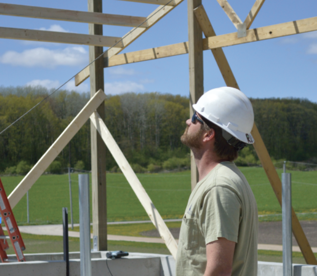
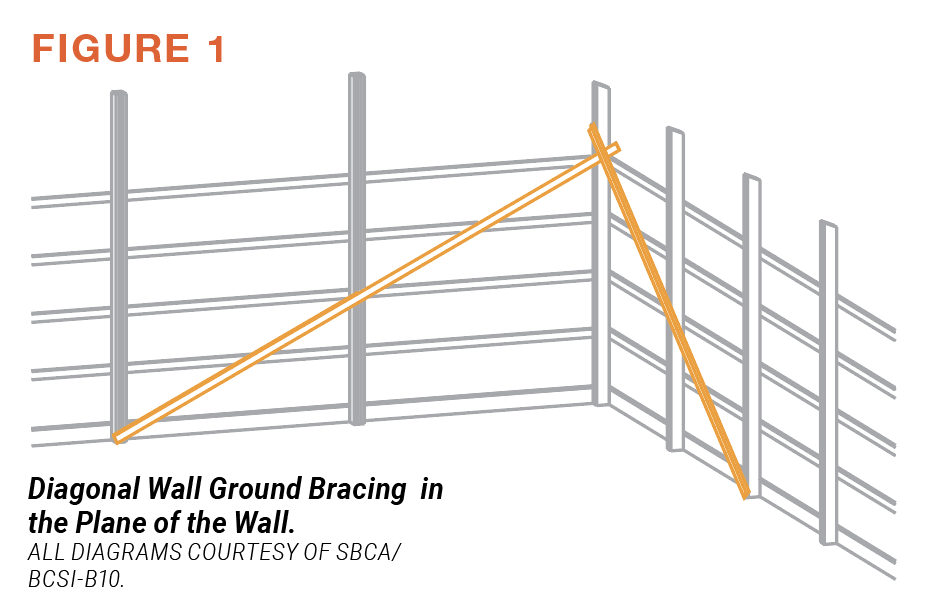
BCSI-B10 provides an alternative approach, specifying diagonal wall ground bracing in the plane of the walls, as well as perpendicular to them (Figures 1 & 2).
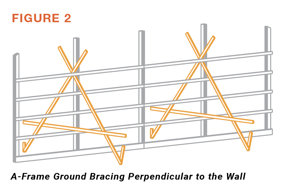
In addition, it is advisable during installation to install column-truss diagonal braces (Figure 3), or affix chains or cables together with turnbuckles or come-alongs, to resist movement of the wall base parallel to the end wall.
Restrain and Brace Your Truss System
With the wall bearing sufficiently braced, the individual roof trusses will also need to be braced and restrained during installation to avoid out-of-plane buckling.
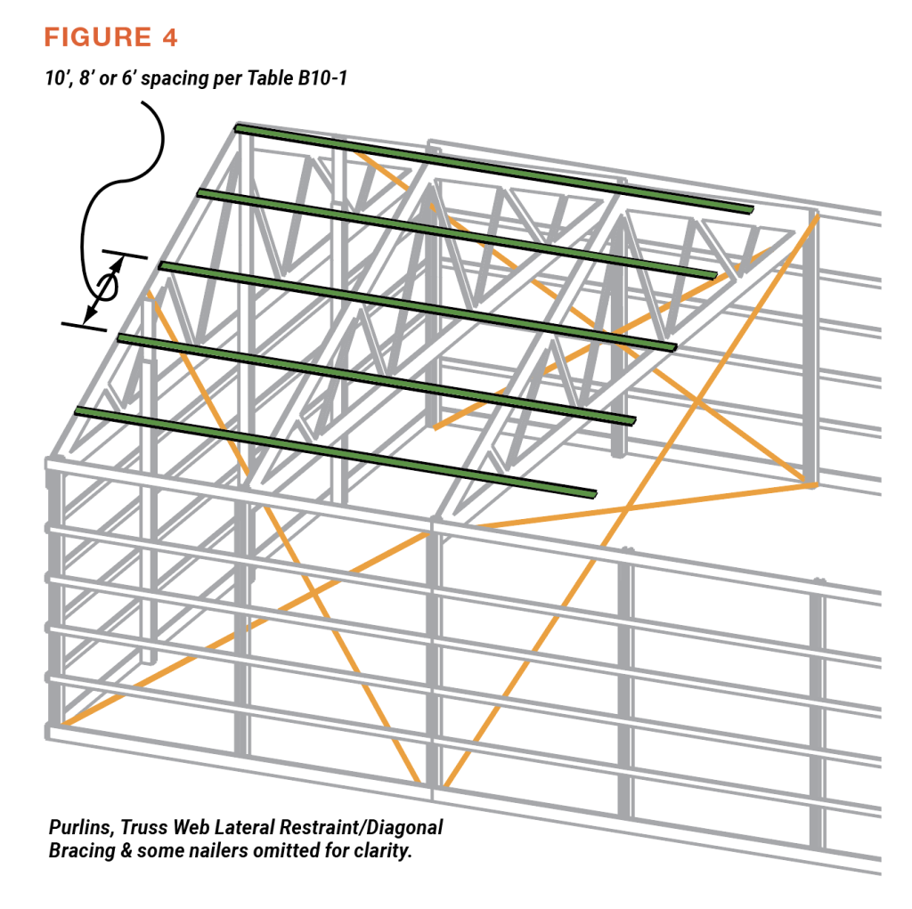
BCSI-B10 provides guidance on installing top chord temporary lateral restraint (TCTLR), which may be spaced 6’, 8’, or 10’ apart along the length of the truss top chords (Figure 4). It’s important to note that TCTLR should be applied using a minimum of 2-16d nails or equivalent, unless otherwise specified by the building designer.
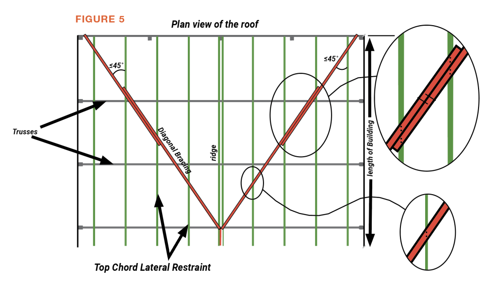
In addition to the TCTLR, diagonal bracing needs to be applied to the top chord plane of the trusses to resist lateral movement of the entire roof truss system during installation. Diagonal braces should be applied to the TCTLR and run the span of at least four trusses on a building over 48’ wide. It’s important to note the diagonal bracing should also overlap, spanning two TCTLRs (Figure 5).
As an alternate to the diagonal bracing, permanent structural sheathing (e.g., plywood, OSB, corrugated aluminum, etc.) can be installed to provide this same resistance to lateral movement. Simultaneously, a similar approach to bottom chord temporary lateral restraint and diagonal bracing should be followed.
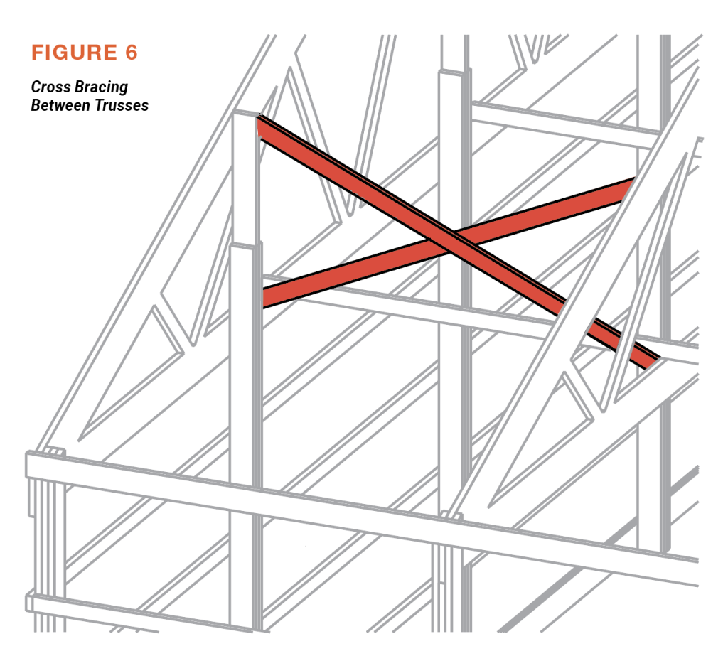
Finally, consider bracing trusses vertically to prevent rollover, or rotation, during installation. This can be done by installing cross bracing between trusses (see Figure 6).
Use Sufficient Bracing
At first glance, all of this top chord, bottom chord, and web member restraint and bracing guidance may appear to be overly conservative. It’s important to note that while BCSI-B10 is a very effective guide on how to approach temporary field bracing, it is not purely prescriptive because it is written to apply to a wide array of building types and construction methods contained within the frame-building industry.
As such, it remains up to the individual installer to determine which restraint and bracing approach is best suited for a particular building. The end goal is to “rescue” each of the long-span roof trusses from the island they are on when being installed more than 2’ o.c. The multi-directional forces acting upon each truss as it’s being handled during installation (e.g. wind, gravity, etc.) can quickly and easily cause a truss to bend out of plane. Once buckling starts, it can be incredibly difficult to counteract before damage occurs to the truss, the truss system, or the building itself.
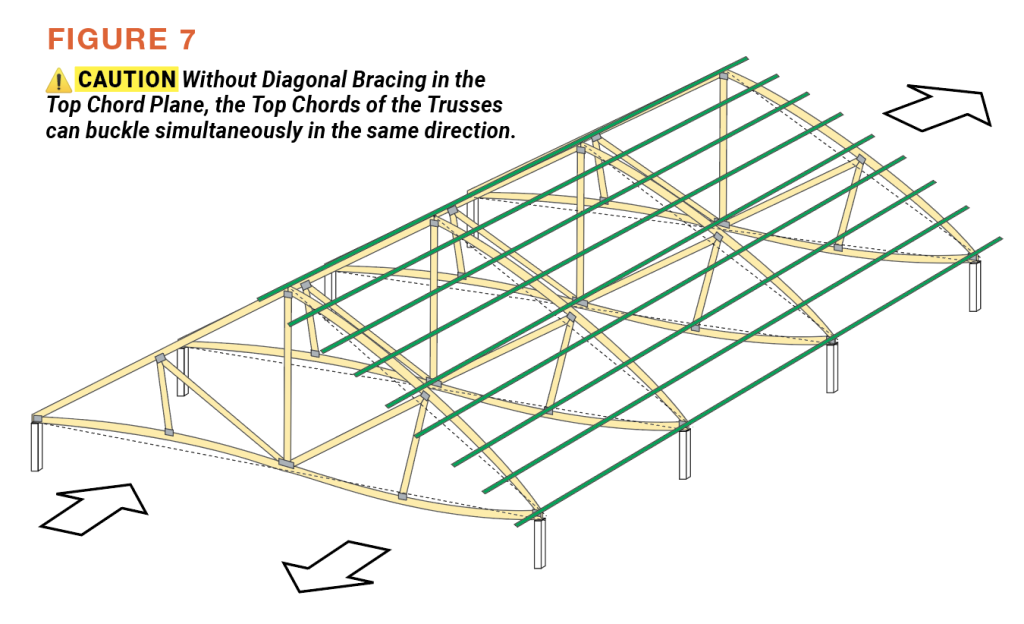
Said another way, the basic approach of applying top chord lateral restraint during installation is typically not enough to ensure truss stability. As BCSI-B10 points out, this approach can too often make a bad situation worse in that the buckling of one truss in the system can cause the other trusses in the system to buckle with it (Figure 7). Installing sufficient diagonal restraint is key to avoiding this bad outcome. This is not only true for the top chords, but for the bottoms chords of the trusses as well.
Bottom Line
An individual roof truss is design to perform within a system. During installation, it’s just sitting out on a deserted island and needs to be rescued. BCSI-B10 provides experience-based best practices on how to properly support each long-span truss during installation in a post-frame building to avoid unwanted outcomes such as damage to the truss itself, failure, or collapse. While this guidance may appear conservative, it is up to the installer to work with the building designer to determine the appropriate amount of lateral restraint and diagonal bracing to use during the construction of a particular roof system. FBN
Sean Shields is Director of Communications for the Structural Building Components Association (SBCA, https://www.sbcacomponents.com) and has authored over a hundred articles focused on structural framing and off-site construction since 2004.