Trusses over 60 feet present bracing challenges
By Sean Shields and Kirk Grundahl, P.E.
Originally Published in SBC Magazine (sbcmag.info)
There’s something wrong with your trusses!” It’s certainly not the first thing you want to hear from your customer after dropping off 60′ and 80′ trusses at his job site a few days earlier. But that’s the message Bob Mochinski, Sales Manager of Littfin Truss in Winsted, Minnesota, heard when he showed up for work one day. “I was glad they were only a few hours away, so I jumped in the car and drove up to see the job site for myself,” said Mochinski. This was fortunate, because Littfin regularly delivers trusses to the North Dakota market over 600 miles away.
Upon arrival, he knew immediately what the problem was: inadequate bracing. How Mochinski dealt with the situation, and what he has to say about educating framers installing long-span trusses (60′ and over), is worth contemplation.

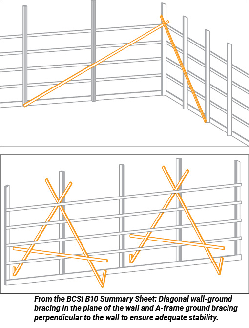
FIGURE 1
One Stiff Breeze
“When I got to the job site, I was pleasantly shocked the building was still standing,” said Mochinski. “There were wires and ‘come-alongs’ all over the building, but nowhere bracing.” Littfin supplied a Long Span Job Site Package with the delivery of components, but its best-practice guidance hadn’t been followed. The BCSI B10 Summary Sheet, “Post Frame Truss Installation, Restraint & Bracing,” outlines in a step-by-step process the bracing that needs to be put in place as long-span trusses are installed.
[columns size=”1/3″ last=”false”]PHOTO 1[/columns][columns size=”1/3″ last=”false”]PHOTO 2[/columns][columns size=”1/3″ last=”true”]PHOTO 3[/columns]
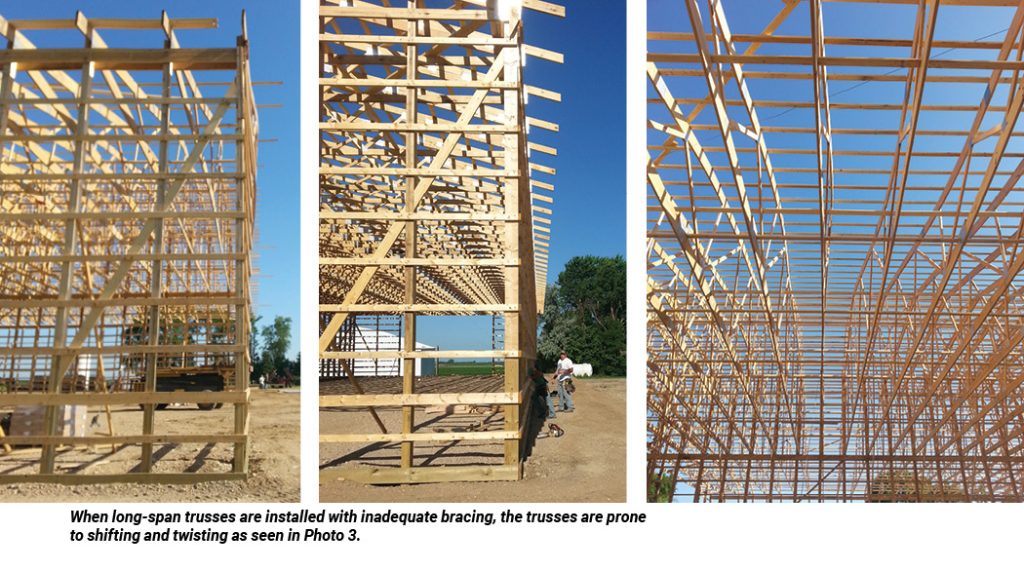
For instance, Step 1 of B10 states, “Ensure stable side-wall and end-wall columns.” It includes the illustrations shown in Figure 1, which depicts how to install diagonal wall-ground bracing in the plane of the wall and A-frame ground bracing perpendicular to the wall to ensure adequate stability. Instead, Mochinski saw walls lacking much in the way of bracing (see Photos 1 and 2).
Fortunately, for the most part, the walls were still relatively in plane. However, the roof trusses had begun to buckle (see Photo 3). When taking Photo 3, Mochinski stood directly below the truss in the middle of the picture. All he should have seen was the profile of the bottom chord; instead, he could see a good deal of the truss, as it had twisted out of plane by over a foot.
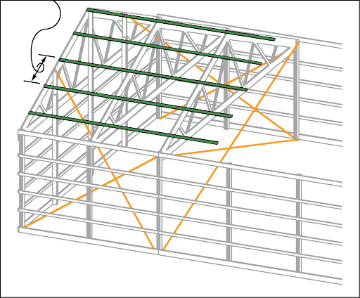
FIGURE 2. From the BCSI B10 Summary Sheet: Top chord temporary lateral restraint guidelines.
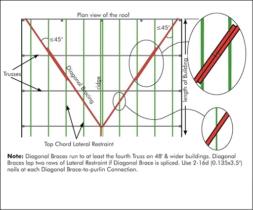
FIGURE 3. From the BCSI B10 Summary Sheet: Top chord diagonal bracing using 2″ x 4″ lumber.
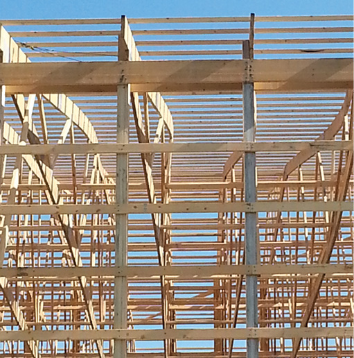
PHOTO 4. While the guidance on installing purlins along the top chords was followed, the step on installation of diagonal bracing of the purlins had not.
Step 3 in B10, which provides guidance on installing purlins along the top chords (see Figure 2), was followed (see Photos 3 and 4). Unfortunately, the next part of Step 3, which calls for the installation of diagonal bracing of the purlins (see Figure 3) had not been followed. It’s important to note that, while this bracing can be installed above or below the purlins, for ease of installation, the temporary diagonal bracing generally is affixed below the purlins so the diagonal bracing can remain as part of the roof system’s permanent bracing and does not have to be removed during the sheathing process.
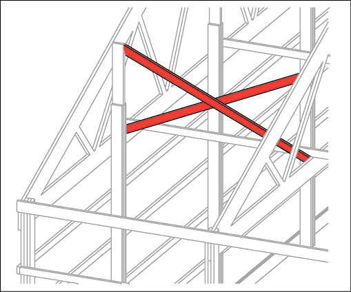
FIGURE 4. From the BCSI B10 Summary Sheet: Cross bracing installed between the trusses.
The guidance on how to install cross bracing between the trusses also went unheeded (see Figure 4).
“The framer told me everything had looked perfectly plumb when he went home the night before,” said Mochinski, “But when he showed up the next morning, everything had shifted. He was adamant there was something wrong with the trusses we had supplied him.” The lumber yard immediately asked Littfin to supply a whole new set of trusses for the job. “I knew there wasn’t anything wrong with the trusses, so I offered to send a professional engineer to inspect the building and provide his analysis.”
At first, they were hesitant, but eventually they agreed to abide by the determination of the P.E. Even though the analysis came with a cost, it supported Mochinski’s assertion that inadequate bracing was to blame.
What was truly miraculous was that the building did not actually collapse. It stood among acres and acres of alfalfa, with nothing around to protect it from the wind. Structural studies like “Lateral Movement of Unbraced Trusses During Construction by David R. Bohnhoff, published by the American Society of Agricultural and Biological Engineers (ASABE), have determined that, prior to sheathing, a building is as vulnerable as it will ever be to wind loading. Given the lack of bracing, one stiff breeze would have possibly been enough to blow the entire building over. Fortunately, for four days, the winds remained still.
[blockquote align=”center” author=””]
Failure From Compression Chord Buckling
Trusses require careful lateral bracing during construction to prevent lateral buckling of the compression chord(s), due to the combination of axial forces induced by the truss’s own deadweight, and bending forces resulting from wind-forces.
The probability of failure from compression chord buckling increases as truss span increases. This is due to a combination of the following interacting factors:
- Chord axial forces due to truss deadweight increase with span.
- Longer span trusses exhibit greater out-of-plane movement. Note: Deflection of a simply supported beam subjected to a uniform load is directly proportional to the fourth power of the span, when cross-sectional area remains constant with length.
- Longer span trusses have larger chords and generally larger and longer webs. This translates into increased surface area and weight per foot of span. The greater the surface area, the greater the wind-force that acts to laterally bow the truss out of plane.
- The more weight per unit length, the greater the gravitational force that works to overturn/collapse the truss as it bows out of plane.
- Longer trusses tend to be taller. Not only may this subject the top of the truss to higher wind–forces, but for trusses only fixed from out-of-plane movement at their bases (i.e., heels), the overturning moment about the base is increased.
[/blockquote]
Long Spans Require Special Consideration
The building itself wasn’t unique for agricultural post-frame construction. It measured 140′ wide by 160′ long. “Historically, 25% of our production volume is this type of construction,” said Mochinski. Over the 140′ span, there was one bearing wall, so the roof profile was split into sets of roof segments—one using 60′ clear span trusses and the other 80′ clear span trusses. The trusses were built as a carrier truss and piggyback truss system as well, with the depth of the carrier truss 14′ high and the piggyback truss completing the roof profile.
[columns size=”1/3″ last=”false”]PHOTO 1[/columns][columns size=”1/3″ last=”false”]PHOTO 2[/columns][columns size=”1/3″ last=”true”]PHOTO 3[/columns]
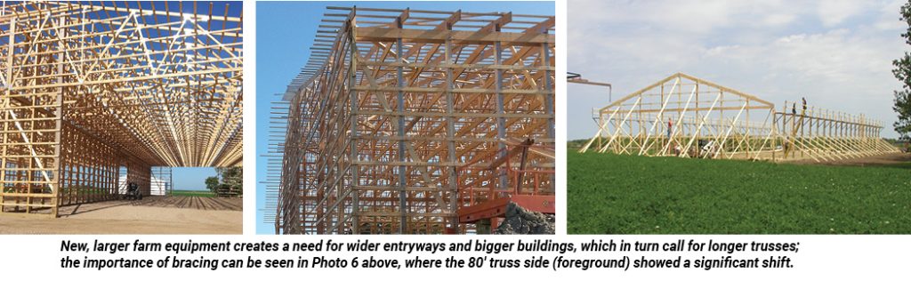
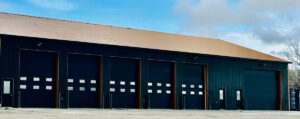
This type of building is being constructed throughout the farm belt as production farming and agricultural equipment gets larger and larger. “The newest farm equipment doesn’t fit in the old sheds, so they need to build them bigger,” said Mochinski. “It’s no longer uncommon to do jobs with truss spans over 100′.” Those long spans allow for large entryways (see Photo 5), but they also require special attention to the design of the building and the entire installation process.
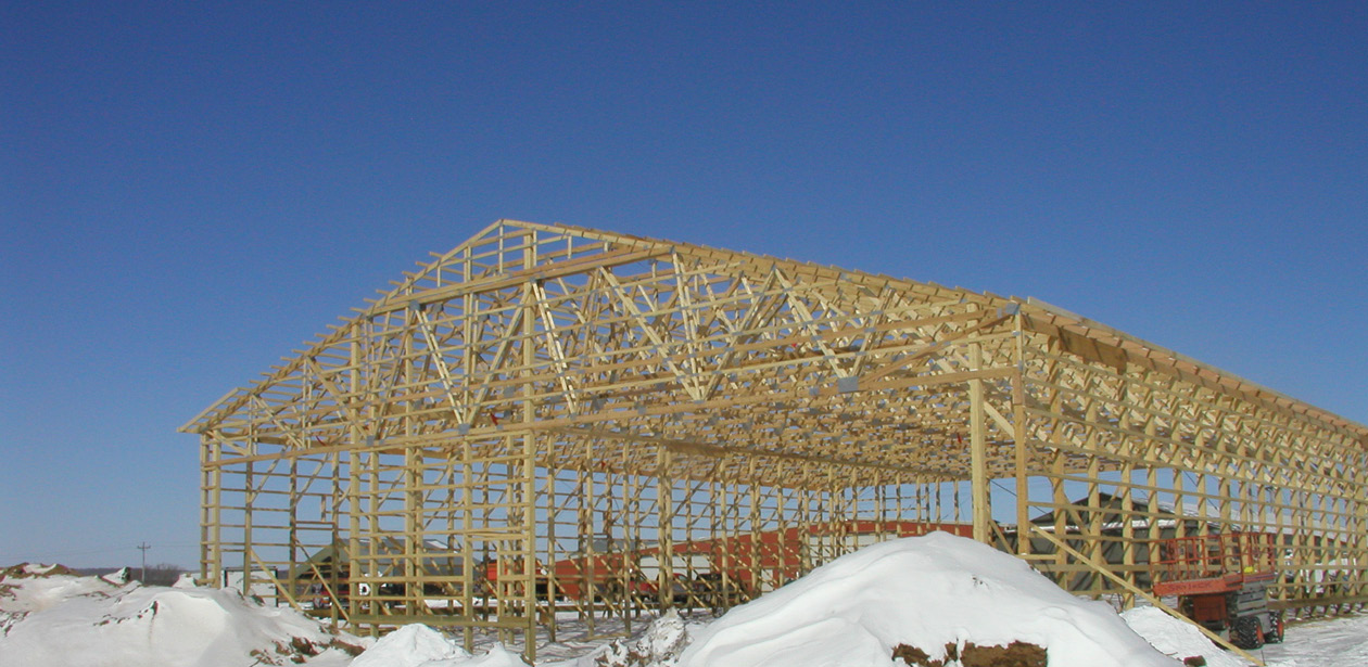
This particular building makes an interesting case in point. “The 60′ truss side of the building showed only minimal shifting,” said Mochinski (see Photo 6, background). “Whereas, the 80′ truss side showed a significant shift.” (Photo 6, foreground). This makes sense, given the ASCE report’s conclusions (see sidebar on page 33), which state that the longer and heavier the truss, the greater the forces pulling the truss further out of plane once the truss begins to move out of plane.
In its first warning to installers, the B10 Summary Sheet states: “Trusses with clear spans 60′ or greater are extremely dangerous to install and require more detailed safety and handling measures than shorter span trusses. Hire a registered design professional (RDP) to provide a restraint/bracing plan and to supervise the erection process.”
Further, the ANSI/TPI 1-2007 standard states in Chapter 2, Section 2.3.1.6.1, which addresses Long-Span Truss Requirements: “In all cases where a truss clear span is 60′ or greater, the Owner shall contract with any Registered Design Professional for the design of the Temporary Installation Restraint/Bracing and the Permanent Individual Truss Member Restraint and Diagonal Bracing.”
Chapter 2 goes on to say, in Section 2.3.1.6.2: “Special Inspection. In all cases where a truss clear span is 60′ or greater, the Owner shall Contract with any Registered Design Professional to provide special inspections to assure that the Temporary Installation Restraint/Bracing and the Permanent Individual Truss Member Restraint and Diagonal Bracing are installed properly.”
Both B10 and TPI 1 are clear that the owner of the building is responsible for hiring an RDP, given the complexity of the design and installation process for long-span trusses. It’s a service component manufacturers can choose to offer their customers, to foster a good working relationship. However, it can be a costly service for the manufacturer to provide and the owner to pay. “For the jobs we ship 600 miles away, it’s not practical to send an RDP all the way out to the job site,” said Mochinski.
Knowledge Is Power
When you talk about the construction industry today, Mochinski is quick to point out that, for many young framers, long-span trusses are almost like a new product. “During the recent recession, we lost a whole generation of old, experienced framers who either retired early or found jobs in other industries,” said Mochinski. “With the construction industry picking up, young guys are starting framing crews, but the mentors they need for dealing with these large trusses aren’t around.”
As a consequence, buildings like this one get erected without the bracing they need. “The reason the framer insisted there was something wrong with my trusses was because he had built several homes and buildings before and had never had this happen to him,” said Mochinski. “But he admitted he had never built a building anywhere near as large as this one, and that made all the difference.”
What’s Mochinski’s advice? “We all need to educate our framers, particularly the ones installing long-span trusses.” Don’t just hand them a Long Span Job Site Package. Take some time prior to delivery and installation to walk them through the industry best-practice guidance contained in the Summary Sheets. Further, continue to remind them of the importance of hiring an RDP, and know how to implement the bracing plan once it is created.
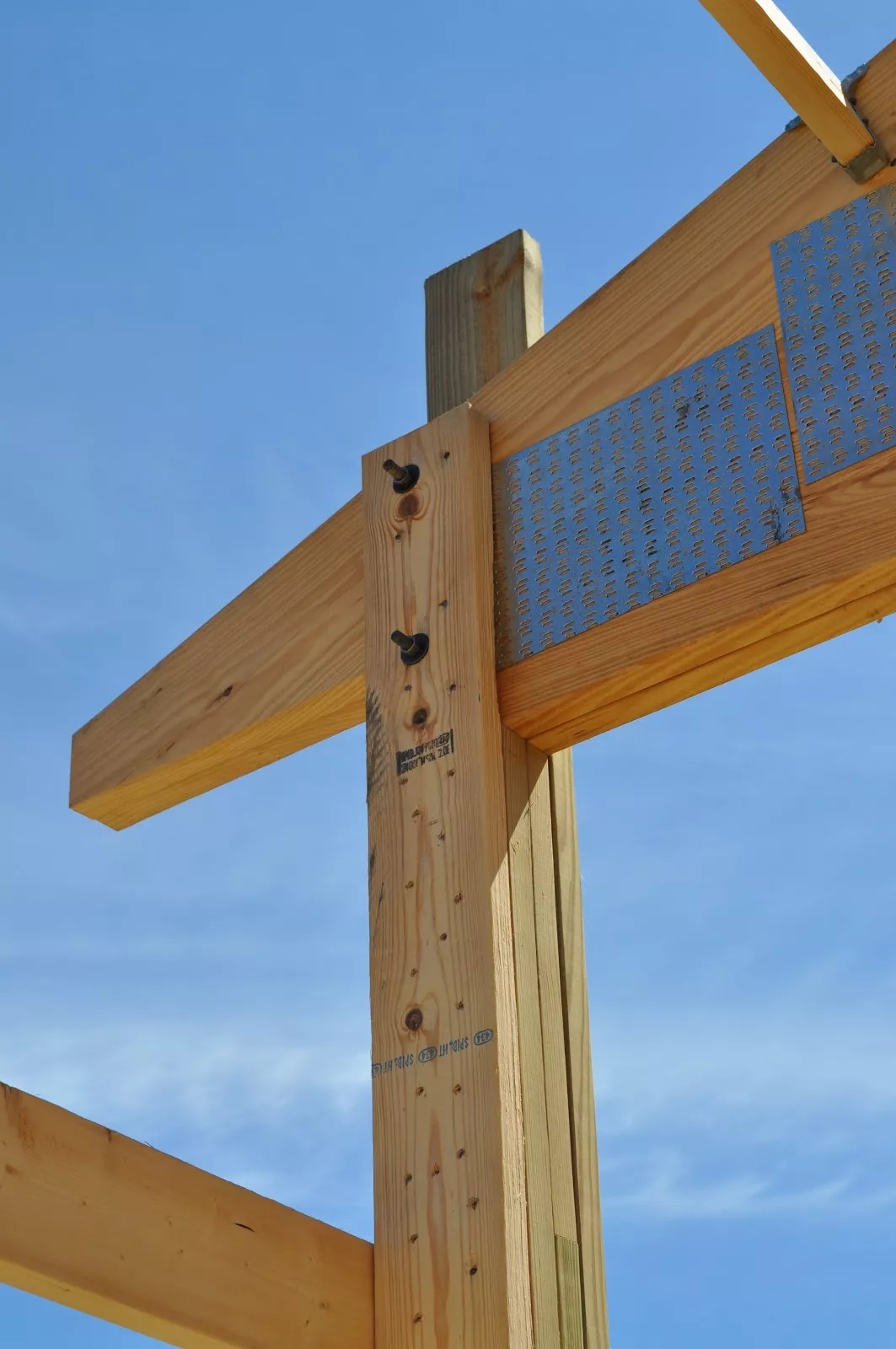
Mochinski is quick to point out that Littfin works with several experienced framers who know what needs to be done as far as bracing, whether it’s walls (see Photo 7) or truss systems. “I have never gotten a call from them saying there’s something wrong with my trusses,” laughed Mochinski.
The framer on this job learned the hard way. Fortunately, the building stayed upright and none of the trusses were damaged. Still, it took the framing crew four additional days to brace the trusses, get the building back to square, and sheath it properly. Littfin, wanting to preserve their relationship with their customer and the framer, provided assistance in remedying the problem. “It goes to show that being proactive and taking the time upfront to ensure they know how to install our products properly is a worthwhile investment.” FBN