By Mike Momb
When I first became involved with post frame construction 43 years ago, nearly every building we provided was for cold storage or utility usage. Very few clients wanted windows and for those who did, single-pane, aluminum frame sliding windows — field-wrapped with steel J-channel trim — were considered sufficient.
After having a plethora of them break during transportation, we upgraded to dual-glazed aluminum windows. This was not for the benefit of energy savings, but because they were so much sturdier. I don’t believe I ever ordered a vinyl window until becoming a post-frame building contractor a decade later. We would use standard flanged vinyl windows, just like those stocked and sold at major lumber retailers and big box stores.

Vinyl windows were a huge upgrade for our clients; however, to flash them it still required cutting and carefully fitting four pieces of steel J-channel trim around them, adding copious amounts of caulking at all corners. We would then do appropriate chants and offerings in hopes we would not end up with leaking windows.
As luck, or lack thereof, would have it, even with best installation techniques, about one in 10 of them would leak. These leaks became painfully expensive, as it meant having to send someone back for a repair.
When we discovered we could order these windows with integral vinyl J trims, our crews loved them. Installation times were greatly improved and now very rarely was there a leak call back. Even using windows with integral J channels, at window lower corners, a potential for leaks still occurs. If a steel high rib ends up at exactly a wrong point, an opening could be left where water can get into building.
The solution remained (as previously done) to goop on lots of caulking prior to installation of siding, and hope.
Window Choices
Before offering solutions to potential leakage challenges, walls must be properly framed. In today’s world, most post-frame buildings are now conditioned buildings, with interior finishes. Many of these are homes and commercial buildings. This makes understanding how International Energy Conservation Code (IECC) requirements impact what all of us should be providing to best meet our client’s (and Code) needs.
Two important things to be looking for when considering window choices — U-factor and solar heat gain coefficient (SHGC).
U-factor is an inverse to R-value. Window U-factors measure how well a window insulates. A lower U-factor means a better insulated window. The 2021 IECC Table R402.1.2 provides maximum assembly U-factors for residential fenestration (windows) ranging from 0.50 in Climate Zones 0 and 1 to 0.30 in Climate Zones 3 and greater.
SHGC values for residential construction range from 0.25 in Climate Zones 0 through 3 to 0.40 in Climate Zones 4 and 5. There is no current SHGC requirement for Climate Zones 6 and greater.
Commercial U-factors and SHGC are far more complex. The 2021 IECC Table C402.4 provides an in-depth breakdown of requirements, not only by Climate Zone, but also whether windows are fixed, operable or in an entrance door or are a skylight.
If in doubt, provide windows with both low U-factors and SHGC values.
Window Framing & Deflection
Once window thermal performance requirements are met, we move to properly framing a wall to accept window openings. The 2021 International Building Code (IBC) Table 1604.3 outlines allowable deflection limits for various building portions. For exterior walls with flexible finishes, wind load deflection is l/120.
Per Footnote “a”
“For structural roofing and siding made of formed metal sheets, the total load deflection shall not exceed l/60. For secondary wall members supporting formed metal siding, the design wind load deflection shall not exceed l/90.”
Footnote “f” states
“The wind load shall be permitted to be taken as 0.42 times the component and cladding loads … Where framing members support glass, the deflection limit therein shall not exceed that specified in Section 1604.3.7.”
From 2021 IBC Section 1604.3.7, “The deflection of framing members supporting glass subjected to 0.6 times the “component and cladding” wind loads shall not exceed either of the following:
1. 1/175 of the length of span of the framing member, for framing members having a length of not more than 13′ 6″.
2. 1/240 of the length of span of the framing member +¼ inch, for framing members having a length greater than 13′ 6″.
To meet these more stringent deflection criteria requirements, it may become necessary to employ bookshelf style wall girts, rather than externally mounted girts. To prevent undue sagging of bookshelf girts below window openings, an appropriately sized and strong externally mounted wall girt may be added directly below bookshelf girt supporting window opening, as an “L”. Your engineer can review designs to ensure Code mandated requirements are being met.
Window Leak Prevention
I have seen all sorts of alternative flashing ideas. Some work; most do not.
The most popular is to use a Z, base, or head trim across top of a standard window, rather than a J-channel. While eliminating water from sitting in a J and reducing amount of water flowing down the side Js, it creates two new leak points — one at each end of trims where they are cut into siding.
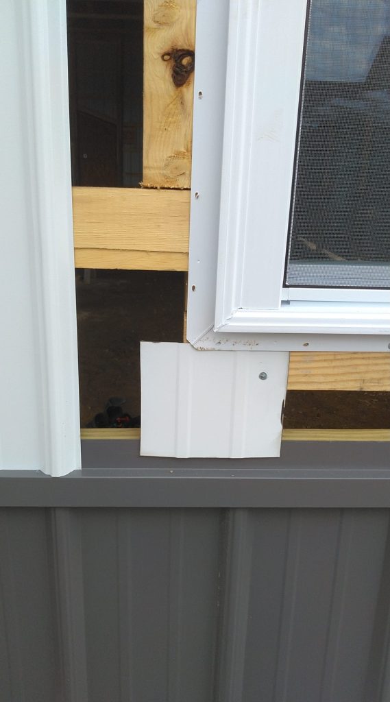
Rather than trying to defeat water entering at window lower corners, some builders opt to just allow water to run down inside of steel siding and out on top of base trim (or wainscot Z trim). Builder Roger Higginbotham places a small piece (or strip when there is no wainscoting) of scrap steel under window corners and overlapping trim below (see photo).
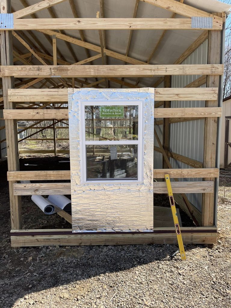
Builder Kevin Delay’s company orders new construction windows with integral J-channels. They place Plyfoil reflective radiant barrier around the window opening, extending down, and overlapping the trim below (see photo).
A concern with these methods is when inside closures are placed between bottom edge of steel siding and trim — trapping water inside the wall.
Installation Tips
We want to use a Weather Resistant Barrier (WRB) in any instance where the client will not be utilizing closed cell spray foam insulation applied directly to the interior face of steel siding. Rather than making an X or I cut at the window opening, cut along all four edges and remove the cutout. Do not wrap WRB into the opening. At the upper corners of the opening, make a slit in the WRB 6″ inches long, upward at a 45-degree angle, away from the opening. Temporarily fold this newly created flap upwards.
Other Tips and Tricks
• Install a sloped sill pan across bottom of window opening.
• Examine window corners for excess vinyl on the face of flanges. This may cause steel siding to lay other-than-flat if not removed. Use a grinding wheel to remove any excess vinyl so the flanges outer face is left smooth.
• A generous door and window sealant bead is run between the window flange and outside of WRB (or window framing if no WRB) at edge of opening sides and top. After the window is properly placed in opening, install self-adhesive flashing tape around window, overlapping tape onto the flange and WRB, working from bottom upwards. Fold down the previously created top WRB tab and tape 45-degree cuts.
• Place form-fitted, adhesive-backed inside closure strips across the window bottom where the steel panel top edge will land.
• Cut steel siding panels to allow for 1/4″ of space between the final panel placement and the recess of the integrated J-channel. Directly above and below the window, place #12 x 1 1/2″ diaphragm screws on each side of every high rib into the underlying wall girt or other horizontal framing member.
• There is a trick for installing steel wall panels into integral J above and below windows. Slide the overlapping panel close to the underlapping panel. Tilt the panel slightly to begin overlap at the point most distant from the window to begin overlap.
• Progress toward the window, along the lap, continuing to slide and straighten at same time. When the overlapping process begins to take some extra effort, slip a putty knife or similar thin, flat surface between the overlap/underlap to create a “ramp” to slide the overlap across underlap. FBN
Mike Momb has been Technical Director for Hansen Pole Buildings, LLC of Browns Valley, Minnesota for more than 20 years. His daily post-frame blog, as well as his weekly “Ask the Pole Barn Guru” column can be followed at the company website, www.HansenPoleBuildings.com/blog/.