By Dave Bohnhoff, PhD PE, Professor Emeritus, University of Wisconsin–Madison
Editor’s Note: This is part two of a two-part series that was originally published in Frame Building News in 2010. It addresses below-grade insulation inquiries we’ve received since the article was first published.
CLICK TO READ PART 1 • CLICK TO download the original article

Below-grade insulation for post-frame buildings is installed to prevent structural damage from frost heave and to minimize building operating costs associated with excessive heat transfer. Causes of frost heave and options for controlling it were presented in Part I of this article, which was reprinted in the June 2021 issue of Frame Building News. Presented in this final portion of the article are requirements for heat transfer control, as well as design details and associated constructability issues for below-grade insulation of buildings with embedded posts.
Introduction
Heat is technically defined as flow of energy due to a temperature variance. In buildings that are warmed or cooled (known as conditioned buildings), control of this energy transfer is a major design element. Although we have a long history of using thermal insulation to control heat transfer through above-grade building assemblies, use of thermal insulation to control below-grade heat transfer is a more recent development.
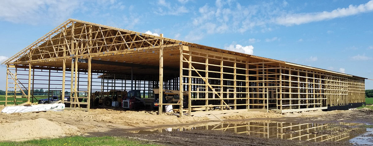
As was noted in the first article, virtually all conditioned post-frame buildings feature a concrete slab. For this reason, the location of below-grade thermal insulation in post-frame buildings is generally described relative to the concrete slab.
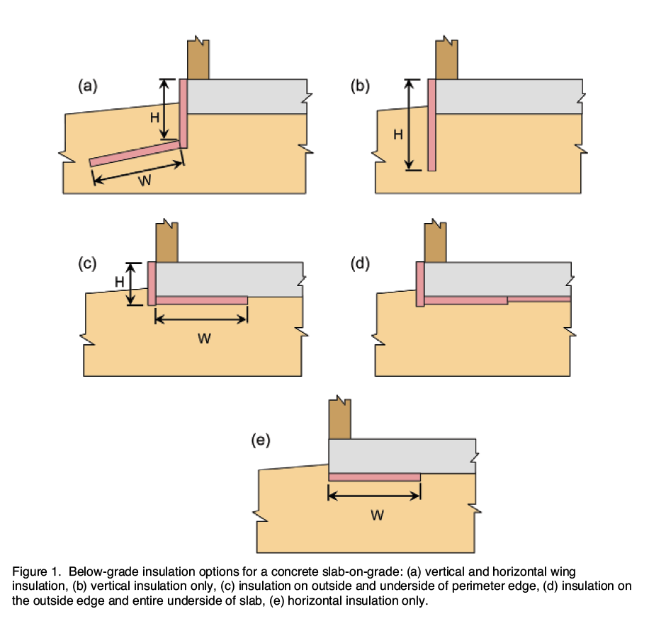
Five common insulation placement options are shown in Figure 1. This includes systems that utilize exterior horizontal wing insulation (Figure 1a), systems that feature only vertical exterior insulation (Figure 1b), systems in which insulation is placed under the concrete slab (Figure 1c and Figure 1d), and systems with horizontal insulation only (Figure 1e).
Quantifying heat loss
In order to efficiently insulate a building, an accurate estimate of heat transmitted through various elements of the building’s thermal envelope (above-grade walls, windows, roofs, opaque doors, etc.) is required. The heat transmittance per unit time through such an element (including the transmission of heat through the boundary air films on both sides of the element) that is induced by a unit temperature difference between the environments on both sides of the element, is defined as the U-factor or thermal transmittance of the element.

Common units on the U-factor are Btu/(h•ft2•°F). It follows that heat being transmitted through an element is obtained by multiplying the element’s U-factor by the element’s surface area and by the difference between inside and outside building air temperatures.
When air infiltration is blocked, heat transmission through an above-grade building element is fairly constant across the surface of the element; hence the U-factor does not vary appreciably with location. This is not the case for below-grade building elements. The amount of heat transmitted through a below-grade element depends on surrounding soil temperatures, which in turn depends on distances between the point in question and (1) the soil surface, (2) the ground water table, (3) surrounding buildings, and (4) other elements of the same building.
F-factors
Accurate determination of variations in heat transmission from location-to-location on a below-grade building element requires a three-dimensional thermal analysis with a fairly sophisticated piece of software. To avoid conducting such complex analyzes for every slab-on-grade floor, F-factors have been developed.
The F-factor for a slab is an approximation of the total amount of heat transmitted through the slab expressed per unit length of slab perimeter. Common units on the F-factor are Btu/(h•ft•°F). To estimate the heat being transmitted from an entire concrete slab-on-grade floor, the F-factor for the slab is simply multiplied by the slab’s perimeter length and by the difference between inside and outside building air temperatures.
F-factors for concrete slabs-on-grade are determined via computer analyzes and depend on such design variables as soil thermal conductivity, soil thermal mass, insulation thermal resistance, insulation location, whether the slab is heated or unheated, slab position with respect to grade, location of the ground water table, slab area, slab shape, shading of the soil surface, and proximity to other building foundations that heat/cool the soil.
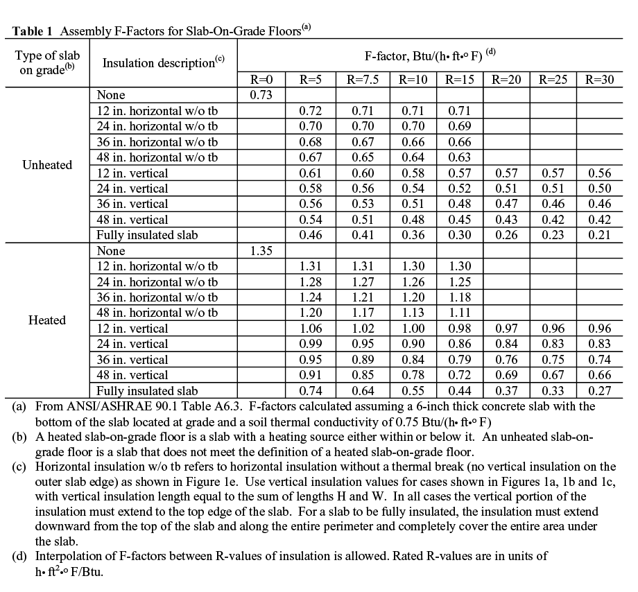
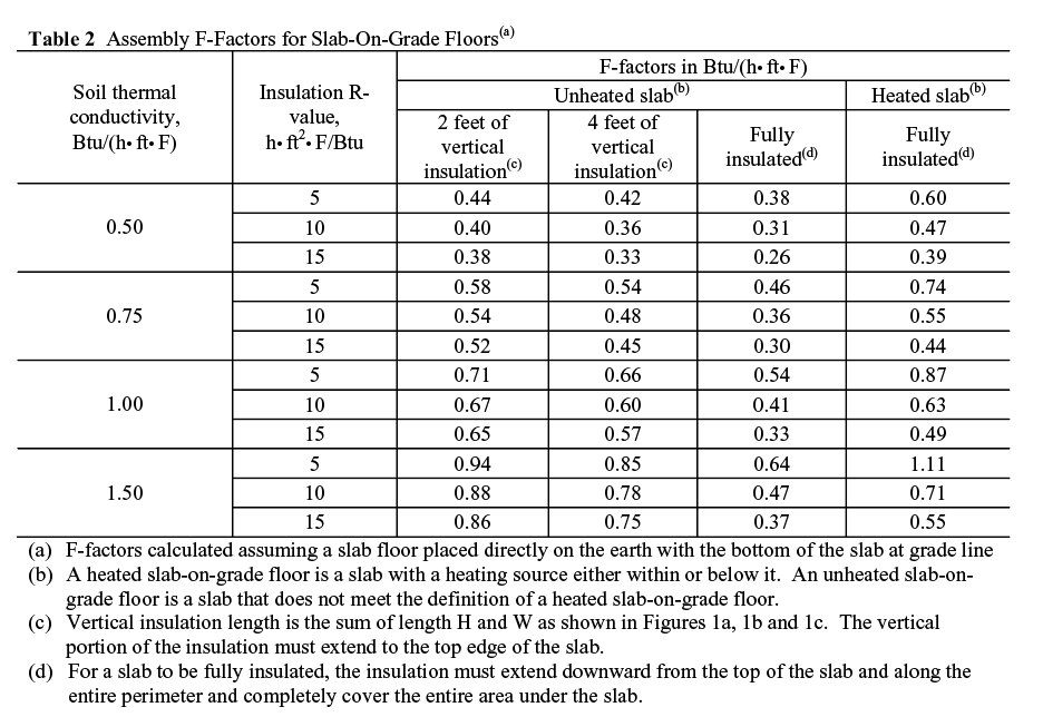
Table 1 contains F-factors for slab assemblies as published in Table A6.3 of ANSI/ASHRAE 90.1 Energy Standard for Buildings Except Low-Rise Residential Buildings. These F-factors are from research conducted by Ecotope Inc. of Seattle, Washington. The slab model was developed in 1988 by Mike Kennedy, who, along with fellow Ecotope coworkers David Baylon and Jonathan Heller, conducted numerous simulations over the next couple of years. The Ecotope group established their F-factors using climate data for typical 8-month heating seasons in Washington State. Table 1 values are for a soil thermal conductivity of 0.75 Btu/(h•ft•°F). Table 2 contains F-factors generated by the Ecotope researchers for other soil thermal conductivities.
Nowhere in Tables 1 and 2 is an adjustment for slab shape or size mentioned. Consequently, a reader is inclined to believe that slab size and shape have only a minor influence on the magnitude of an F-factor. In reality, both slab size and shape can significantly impact the F-factor, as several researchers have shown. The F-factors in Tables 1 and 2 were obtained from simulations involving a residential-sized 30- by 45-foot slab, this since they were generated by Ecotope for use in estimating heat loss from residential buildings. Ironically, the Table 1 values are published in a document titled Energy Standard for Buildings Except Low-Rise Residential Buildings. During a recent conversion that I had with David Baylon on this topic, he warned me that the F-factors in Tables 1 and 2 would do an extremely poor job of predicting heat lost to the soil from very large slab-on-grade buildings (e.g., big box stores).
Insulation location
Not covering the outside vertical edge of a slab with insulation (Figure 1e) significantly increases heat transmission; for this reason, this case is treated independently in Table 1 from those with vertical insulation covering the outside edge of the slab (Figures 1a through 1d).
Vertical insulation length, as specified in the second column of Table 1 and in the header of Table 2, is equal to H as shown in Figure 1b or the sum of lengths H and W as shown in Figures 1a and 1c. In other words, Tables 1 and 2 draw no distinction between the insulation placements shown in Figures 1a-1c. As long as the insulations used in two different systems cover the vertical edge of the slab and have the same R-value and same total length (again, total length equals H+W in Figures 1a and 1c) the total heat transferred by the different systems is assumed to be identical. In reality, there are slight differences in heat transmission between the Figure 1a, 1b, and 1c locations, but the differences are not nearly as significant as the difference between one of these cases and a slab without the outside edge covered (Figure 1e).
Where a concrete slab directly overlies frost susceptible soils in a cold climate region, the insulation systems in Figures 1a and 1b are recommended.
Heated and unheated slabs
F-factors in Tables 1 and 2 are compiled for both heated and unheated slab-on-grade floors. A heated slab is one with a heating source either within or below it. Note that regardless of exactly where the heating source is located, the insulation is always assumed to be between the heating source and soil. An unheated slab-on-grade floor is a slab that does not meet the definition of a heated slab-on-grade floor.
The reason F-factors are higher for heated slabs is because a heated slab will be warmer than the design indoor temperature, and thus for a given indoor temperature, expect more overall heat loss from a heated slab.
Soil thermal conductivity
It is clear from Table 2 that soil thermal conductivity has a significant impact on F-factor values and thus care should be taken into account when estimating this value. Thermal conductivity k is the ability of a material to conduct heat, and although English units on thermal conductivity are identical to those of the F-factor, they really are not identical properties.
Table 3 contains k values for unfrozen soil that were obtained using the relationships at the bottom of Table 3. These equations were published by Sen Lu and colleagues (Lu, 2007). To determine k with these equations only requires knowledge of the soil’s dry bulk density Υd, moisture content w, and quartz content q. Soil dry bulk density and moisture content are used to calculate soil porosity η and degree of soil saturation Sr. Quartz content is used to calculate thermal conductivity of the soil solids ks. Quartz content is the fraction of dry soil that is quartz, and can be approximated as the fraction of the dry soil mass that is sand (although this tends to overestimate ks). Knowledge of the quartz content is important because quartz has a thermal conductivity measureably higher than other common soil minerals.
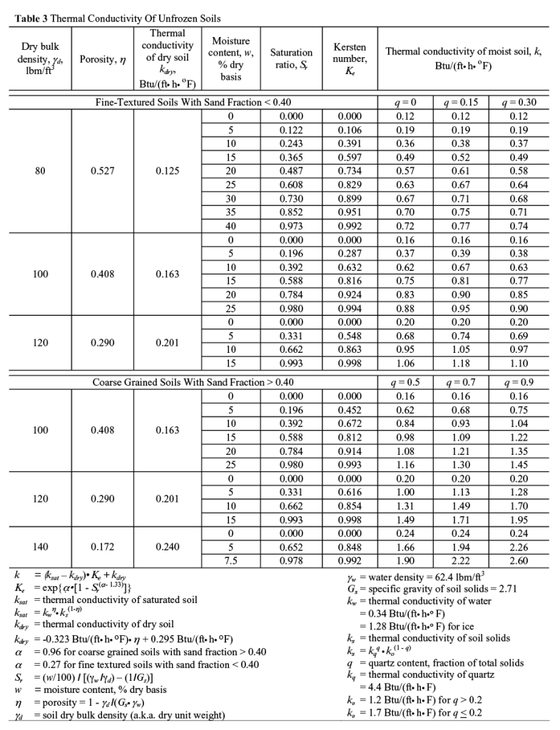
Soil thermal conductivity k is calculated using the thermal conductivity of dry and saturated soil (kdry and ksat, respectively) and a normalized thermal conductivity Ke (i.e., the Kersten number). Note that kdry is calculated from soil porosity η, whereas ksat is a direct function of the thermal conductivity of liquid water kw and the thermal conductivity of soil solids ks. The relative contributions that kw and ks make to ksat is a function of soil porosity. The Kersten Number Ke is a function of the degree of soil saturation Sr and a soil texture dependent parameter a which is set equal to 0.27 for fine textured soils with a sand fraction less that 0.40, and to 0.96 for coarse grained soils with a sand fraction greater than 0.40.
It is evident from Table 3 values that soil thermal conductivity increases with increases in dry bulk density, soil moisture and quartz content. On average, k is greater for coarse soils, largely because of its quartz content and higher dry bulk densities.
At 32 degrees Fahrenheit ice has a thermal conductivity of 1.28 Btu/(ft•h•°F), which is almost four times that of liquid water at the same temperature. For this reason, frozen soil will have a higher thermal conductivity than unfrozen soil of the same moisture content. The difference is relatively minor at low moisture content levels, but can be significant for soils with low dry bulk densities and high moisture contents. To approximate the thermal conductivity of a frozen soil, use the same equations with kw set equal to ice’s thermal conductivity of 1.28 Btu/(ft•h•°F).
In the absence of soil property data, thermal conductivity is generally approximated as 0.75 Btu/(ft•h•°F).
Insulation types
Control of below-grade heat transfer was revolutionized by the development of rigid, plastic foam board insulations. Base plastics include polystyrene, polyisocyanurate (also known as polyiso), and polyurethane. There are two main categories of polystyrene products: extruded/expanded polystyrene (XEPS or XPS) and molded/expanded polystyrene (MEPS or EPS). These two products are discussed in more detail here because they are the most widely used products for below-grade insulation. Polyisocyanurate and polyurethane boards are similar in formulation. They tend to be more expensive than polystyrene-based boards, but can withstand higher temperatures than polystyrene, thus making them more attractive for roofing applications.
XEPS is manufactured by melting polystyrene beads and mixing the resulting liquid with special additives and a blowing agent inside an extruder under a very specific temperature and pressure. The resulting hot viscous liquid is extruded through a die into a reduced-pressure environment, upon which the gaseous blowing agent expands, resulting in the formation of a uniform closed-cell foam sheet with smooth skins. Common trade-named products include Dow Chemical’s Styrofoam (blue), Owens Corning’s Foamular (pink), Pactiv Corporation’s GreenGuard (green) and DiversiFoam Products’ CertiFoam (yellow). MEPS board is produced from polystyrene resin beads that contain microscopic cells filled with a blowing agent (usually pentane or butane). The beads are exposed to steam under controlled pressure. The heat from this steam simultaneously softens the cell walls and expands the blowing agent, causing individual beads to increase in volume by up to 40 times. After a brief holding period to allow stabilization, the expanded closed-cell beads are poured into a large block mold. Steam is injected into the mold, and heat and pressure further expand and fuse the beads into a molded block. These blocks are cooled and then cut with hot wires to make the thinner sheets used for insulation. Because of its manufacturing process, MEPS is frequently referred to as bead board. Most people are familiar with EPS as a packaging product for which it is ideal, because it is lightweight (reduced shipping cost), shock absorbent, nonabrasive, not weakened or damaged by moisture exposure, and insulates package contents from temperature changes.
Specifications for various types of MEPS and XEPS are compiled in Table 4. Note that for a given density, XEPS exhibits a higher thermal resistance, higher compressive strength, lower water vapor permeance, and lower water absorption than MEPS. The lower properties for MEPS are attributable to microscopic pores between the closed-cell expanded beads. Because of the higher water permeance and adsorption of MEPS, there was a widespread belief among many in the building industry that MEPS deteriorated in the presence of wet soils subjected to freeze-thaw cycles. These concerns subsided after some U.S and Canadian field studies conducted in the 1990s showed long-term performance of MEPS to be just as good as XEPS. Today, many of the insulated concrete forms (ICFs) used for foundations are MEPS products.
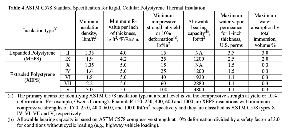
In addition to the physical and thermal properties compiled in Table 4, it should be noted that MEPS and XEPS are unaffected by common soil acids, will not support mildew and fungus growth, and are decay and corrosion resistant.
The downsides of MEPS and XEPS are that they are deteriorated by ultraviolet radiation, easily damaged by certain solvents, melt at temperatures above 250 degrees Fahrenheit, incompatible with certain thermoplastics (polystyrene insulations are known to draw plasticizers out of thermoplastic membranes, causing permanent degradation), flammable, and subject to termite infestations. Where termite infestations are a potential problem, external applications of MEPS and XEPS may be prohibited, the insulations may need to be encased in concrete, or an inspection gap may be required between the insulation and wood-based building materials.
To combat physical damage and deterioration via sunlight, exposed exterior MEPS and XEPS are generally covered with a stucco coating, pressure-treated wood, brick, or aluminum flashing. When installed on the interior of a building, the flammability of these insulations requires that they be protected by a suitable “thermal barrier” or “ignition barrier” in accordance with the applicable code. In most cases, this need is met with a half-inch thick gypsum wall board covering.
Code requirements
Thermal insulation requirements embodied in energy conservation-related codes are largely based on the ANSI/ASHRAE Standard 90.1-2007. There are two different “compliance paths” outlined in ASHRAE 90.1-07: a prescriptive building envelope option and a building envelope tradeoff option.
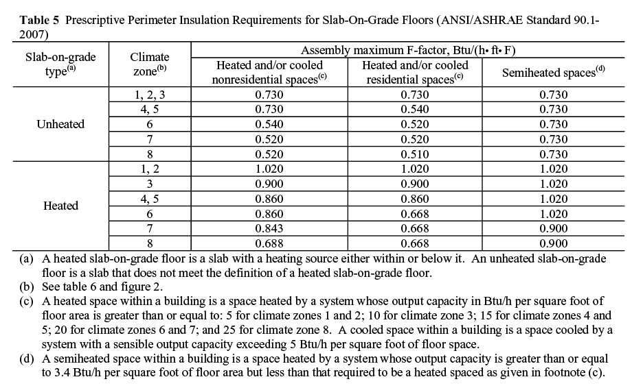
Designers following the prescriptive building envelope option must make sure that each element of the building thermal envelop has a thermal transmittance (i.e., U-factor, F-factor) less than its code-prescribed value. Prescriptive thermal insulation requirements for slab-on-grade floors from ASHRAE 90.1-07 Table 5.5 are given in Table 5.
Designers following the ASHRAE 90.1-07 building envelope trade-off option must make sure the total heat transmission through the entire building thermal envelope does not exceed a code specified value. Via this option, a designer can utilize a concrete slab-on-grade with an F-factor that exceeds the applicable maximum prescribed value listed in Table 5 as long as the total performance of thermal envelope meets code requirements. The trade-off option is popular as it provides greater flexibility in design, which makes it easier to lower overall building cost. Implementation of the building envelope trade-off option is facilitated with spreadsheet programs or special computer programs (e.g., REScheck, COMcheck).
Climate zones
As indicated in Table 5, thermal insulation requirements depend on temperature differences across a building envelope. The greater and more prolonged these temperature differences, the greater the insulation need, and the lower will be the prescribed maximum F-factor. This explains why the prescribed values in Table 5 are lower for heated and cooled spaces than for semi-heated spaces, and why prescribed F-factors are lower for northern climate zones.
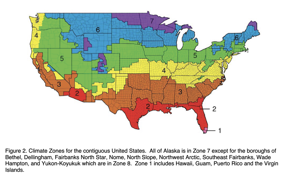
Climate zones referred to in Table 5 are shown in Figure 2 and defined in Table 6. Current zone differentiation is based on work done by Robert Briggs, Robert Lucas, and Todd Taylor of the Pacific Northwest National Laboratory (PNNL). The 2004 International Energy Conservation Code (IECC) Supplement was the first major publication to adopt the PNNL climate zones and it was subsequently adopted by ANSI/ASHRAE 90.1.
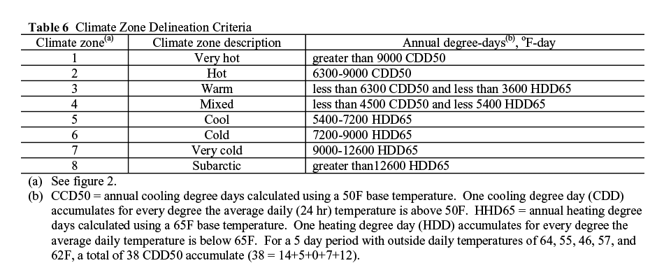
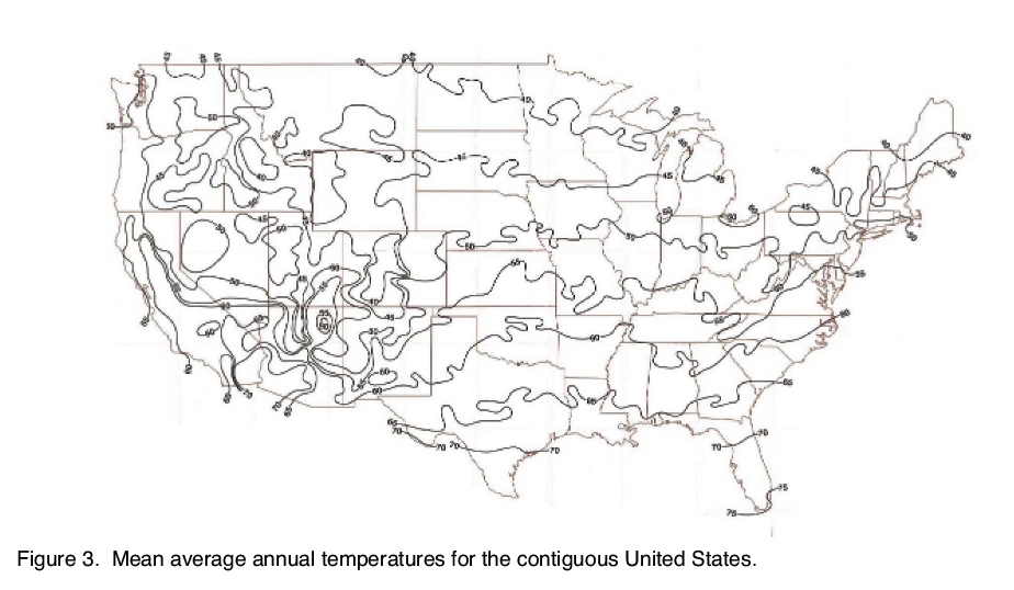
As Table 6 indicates, climate zones are primarily based on heating and cooling degree days. Although degree days dictate above grade insulation requirements, insulation requirements for controlling below-grade heat transfer are largely dictated by soil temperatures and thermal conductivities. Soil temperatures, in turn, are directly related to annual average dry bulb temperatures that are graphically displayed in Figure 3. A comparison of the climate zones in Figure 2 with the isotherms in Figure 3 explains why climate zones can be used to approximate soil temperatures.
Example selection
In accordance with ASHRAE 90.1-07 prescriptive building envelope requirements, what insulation options (total vertical plus horizontal insulation length and insulation R-value) can be used for an unheated concrete slab that supports a heated/cooled building located in climate zone 7 where the soil has a thermal conductivity of 0.75 Btu/(h•ft•°F)?
Table 5 requires that the F-factor not exceed 0.520 Btu/(h•ft•°F). Based on Table 1, this requirement can be met with 24 inches of R15 insulation (F-factor = 0.52), 36 inches of R10 insulation (F-factor = 0.51), or 48 inches of R7.5 insulation (F-factor = 0.51). Alternatively, the entire slab can be insulated with R5 insulation (F-factor = 0.46). Note that the 0.520 Btu/(h•ft•°F) requirement can not be met with an application featuring only horizontal insulation (Figure 1e).
Insulating heated slabs
The rule of thumb for insulation of heated slab-on-grade floors is to increase by 5 h•ft2•°F/Btu the R-value that would be prescribed for the slab if it was not heated, and also install insulation with a minimum R-value of 5 h•ft2•°F/Btu under the remainder of the slab. Please note that a number of energy specialists recommend that the remainder of a heated slab be insulated with an R-value of no less than 10 h•ft2•°F/Btu.
Installing below-grade insulation
Figures 4–6 contain construction details for below-grade insulation of buildings with embedded posts. Prior to discussing these details, I would point out that these details are just as applicable to posts mounted on concrete piers, with the exception that thermal breaks should be added between any concrete slab and concrete pier. I would also note that below-grade insulation details for buildings with posts that are not embedded or are not placed on piers are not included here. Such posts are either placed on concrete stemwalls or slab-on-grade foundation systems, and common practices as they relate to insulating such concrete foundations are widely published elsewhere.
Figure 4 illustrates an insulation system that would not be placed in contact with frost-susceptible soils since soil located directly under the perimeter of the concrete slab could freeze and heave. There is absolutely no problem with this system as long as the concrete slab is placed on well-drained, nonfrost-heave susceptible soils, and the post footing is placed below the anticipated frost depth.
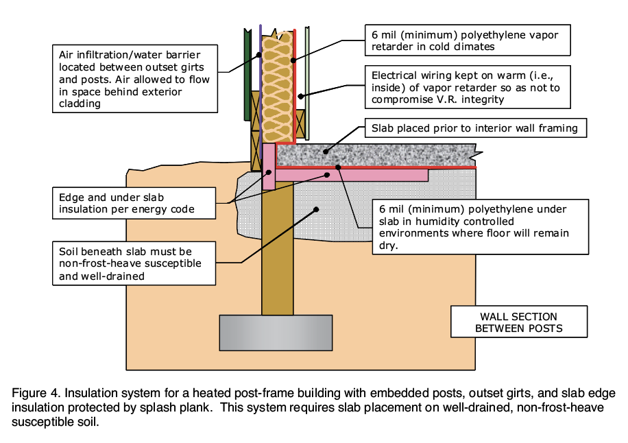
From both a cost and a constructability perspective, the system shown in Figure 4 may be the best way to insulate a building with embedded posts. With the right soils, it is the ideal system for buildings with heated concrete slabs. When installing a heated slab, I strongly recommend placing insulation with a minimum R-value of 10 h•ft2•°F/Btu under the entire interior of the slab. In climate zones 3 and higher, energy codes will generally require that insulation under the exterior perimeter and along the outside edges of a heated slab have an R-value greater than 10 h•ft2•°F/Btu.
Figures 5 and 6 both show systems that can be used for conditioned post-frame buildings with embedded posts and slabs overlying frost susceptible soils. In Figure 5, girts are outset and insulation near grade is protected by splash plank. In Figure 6, girts are inset and insulation is located outside base girts.
The problem with using the insulation systems in Figures 5 and 6 for buildings with embedded posts is two-fold. First, they negate one of the major advantages of the embedded post foundation system and that is minimal excavation. Since below-grade vertical and horizontal wing insulation cannot be installed until after posts (or piers) have been embedded, when is the excavation for the insulation made?
One option is to begin building construction by digging a trench at a depth and width that will accommodate the horizontal wing insulation as well as compaction of soil on the inside of the vertical insulation. Once the trench is dug, post holes can be augered (this has the benefit of decreasing post-hole augering depth).
A second option is to trench alongside the exterior of the building after the exterior shell has been completed, but before interior concrete work has begun. The problem with this option is that there’s no inside trench in which to run the typical compactor that would be used to compress soil against the inside of the vertical insulation.
A third option is to construct the building with the grade at least a full foot lower than the finish grade, with insulation placement done just before soil is added to bring it up to the final elevation. While this requires fill material to be placed inside the structure after the shell is complete, such a sequence may actually be beneficial in buildings featuring extensive under-slab plumbing, electrical, HVAC and other systems.
The second problem with the insulation systems in Figures 5 and 6 when used in buildings with embedded posts involves installation of the vertical insulation. More specifically, how is the soil adequately compacted on both sides of the vertical insulation without compromising the integrity of the insulation system?
With concrete stemwall and slab-on-grade foundations, the vertical insulation is simply compacted against a vertical concrete surface. Such a surface does not exist between embedded posts. When compacting soil, it is important to keep the vertical insulation straight so as to maintain a tight joint between it and the horizontal wing insulation. This can be accomplished by temporarily fastening an inset girt against the inside of the vertical insulation while compacting soil against the outside surface.
Regardless of the insulation method used, make sure that a durable, opaque, weather-resistant covering or coating is used to protect exposed insulation from ultraviolet radiation, physical damage, and other sources of deterioration. Also make sure that compressive loads on insulation materials supporting building foundation loads do not exceed the allowable bearing capacities given in Table 5, and that the surface upon which any horizontal insulation is laid has been struck level. Production of a compact and level surface often requires that the surface be worked with a straight edge in between passes with a mechanical compactor.
Vapor retarding membranes and sand layers
Vapor retarding membranes are placed below concrete slabs to minimize the diffusion of water vapor and other gases from the soil into the building environment. When properly installed they can reduce indoor humidity levels; prolong the life of flooring materials; decrease mold growth potential; and reduce indoor concentrations of radon, methane and other unwanted gases.
In typical construction, a vapor retarding membrane is placed over a layer of pea gravel that serves as a capillary break between the soil and the membrane. After placing the membrane over the pea gravel, some builders cover it with a layer of sand and then place concrete on top of the sand layer. Depending on the intended purpose of the sand layer, it may be referred to as a blotter, cushion layer, or protection course.
The sand layer acts as a blotter when it is relied on to absorb excess water during concrete placement in an effort to reduce bleed water at the concrete surface. Although the term blotter is appropriate for this application, this is not a sound reason for installing a sand layer. Excess bleed water is a symptom of a water-to-cement ratio that is too high, and a sign that the concrete will have a relatively low strength and high permeability when cured.
Additionally, it has been shown to take slabs placed over sand 3 to 4 times longer to dry down to the same point as slabs placed directly on membranes. A prolonged wet slab can negatively impact the quality and schedule of flooring installations. In the end, a builder is much better off spending money on concrete additives and proper concrete curing than on a “blotter.”
Sand layers serve as cushion layers and protection courses when they are installed to prevent accidental puncture of membranes during steel reinforcing and concrete placement. In this case, use of a sand layer can be avoided by using a thicker or more puncture resistant membrane (e.g., 10 or 15 mil polyethylene meeting ASTM E1745 Class A membrane requirements), or in the case of insulated slabs, by placing rigid insulation on top of the membrane. Please note that by placing the membrane on the moist side of the insulation the insulation is less likely to be compromised by water absorption.
Finally, an unlikely but potential problem introduced by placing a sand layer between a vapor retarding membrane and a concrete slab is that should water ever find its way into the sand layer, the membrane will help ensure that the water spreads out in the sand layer and stays there until it diffuses up through the concrete. In this case, the membrane is contributing to a problem that it was intended to help solve.
Summary
Use of F-factors for calculating heat transmission from concrete slab-on-grades was presented. These F-factors are a function of many variables including soil thermal conductivity, insulation thermal resistance, insulation location, whether the slab is heated or unheated, slab position with respect to grade, and total slab area and shape. Methods for calculating soil thermal conductivity were overviewed along with physical and thermal properties of MEPS and XEPS insulations. ANSI/ASHRAE Standard 90.1-2007 insulation requirements for concrete slab-on-grades were introduced, and three details for below-grade insulation of post-frame buildings with embedded posts were discussed, along with disadvantages of introducing a sand layer between a concrete slab and an underlying vapor retarding membrane. FBN
Reference
Lu, S., Ren, T., Yuanshi, G., & Horton, R. (2007). An improved model for predicting soil thermal conductivity from water content at room temperature. Soil Science Society of America Journal, 71, 8-14.
Baylon, D. & Kennedy, M. (2007). Calculating the impact of ground contact on residential heat loss. _Proceedings of the Tenth International Conference on Thermal Performance of the Exterior Envelopes of Whole Buildings X. December 2-7, 2007, Sheraton Sand Key Resort, Clearwater Beach, Florida. Organized by the Oak Ridge National Laboratory (ORNL)