
Preventing Frost Heave
By David R. Bohnhoff, Ph.D., P.E.
Professor Emeritus, University of Wisconsin – Madison
It seems that recently more designers are questioning how to best insulate the foundation of a post-frame building. I attribute this to an increase in the number of heated post-frame buildings being constructed, along with an increased emphasis on reducing heat loss/gain in these buildings.
The latter is fueled by the green building movement and corresponding changes in energy conservation codes.

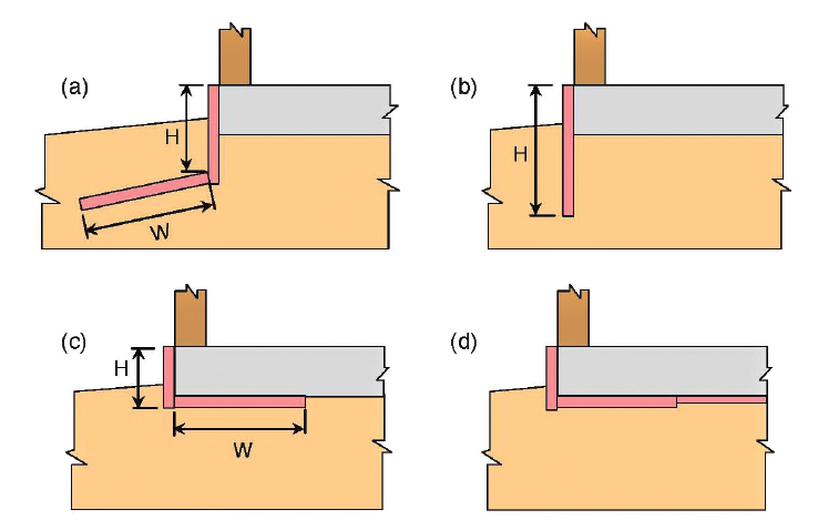
In virtually all cases where a post-frame building foundation is being insulated, the building has a concrete slab. The questions I get generally come from designers who have seen several different systems used to insulate these slabs, including systems that utilize exterior horizontal wing insulation (Figure 1a), systems that feature only vertical exterior insulation (Figure 1b), and systems in which insulation is placed under the concrete slab (Figures 1c and 1d).
Two Design Goals
It’s important to understand that there are two principal reasons for installing below-grade insulation. The first is to control building heat loss/gain in an effort to minimize building operating costs and to reduce consumption of nonrenewable natural resources associated with energy production. The second is to prevent frost from heaving a slab and causing structural damage. The latter is a concern only in colder regions with frost-susceptible soils.
Designs for control of building heat loss/gain are based largely on requirements in American National Standards Institute (ANSI) and American Society of Heating, Refrigerating and Air-Conditioning Engineers (ASHRAE) Standard 90.1-2007 Energy Standard for Buildings Except Low-Rise Residential Buildings.
Designs for minimization of damage due to frost heave are based largely on requirements in Structural Engineering Institute (SEI) and American Society of Civil Engineering (ASCE) 32-01 Design and Construction of Frost-Protected Shallow Foundations.
The fact that SEI and ASCE administer the standard that addresses frost heave and ASHRAE administers the standard that addresses building heat loss/gain underscores the two distinctly different purposes for using below-grade insulation — one structural and one energy related.

This article is the first in a two-part series on below-grade insulation of post-frame buildings. As the title indicates, this first article is dedicated to building design for frost-heave control. The second article will cover design requirements for heat-transfer control, as well as design details for below-grade insulation of post-frame buildings with embedded posts. These design details will be accompanied by a discussion on their constructability.
The Cause of Frost Heave
In areas where average daily temperatures stay below freezing for extended periods of time, soil heaving due to ice segregation can be a major concern. Ice segregation is the formation of discrete ice layers or lenses within the soil due to the migration and subsequent freezing of pore water, which is water in the spaces between soil particles. Frost heaving (also known as soil heaving or frost action) directly results from the fact that water expands approximately 9% in volume when it freezes.
The temperature at which pore water freezes depends largely on solute concentrations. Pore water with low solute concentrations will freeze within a fraction of a degree of 32°F, whereas pore water with high solute concentration may not completely freeze until its temperature has dropped to 25°F.
If pore water present near the soil surface at the beginning of winter were the only water to turn to ice, there would be no real frost heaving issues. Large ice layers and lenses (and hence problems) result when pore water turns to ice and then sucks water from warmer areas by capillary action. The suction that ice exerts on warmer soil water is termed cryosuction. As cryosuction feeds capillary water to the underside of ice layers and lenses, their thickness grows. The term ice segregation is used to describe this ice formation action because it segregates regions of previously mixed soil and water into regions of ice and dry soil.
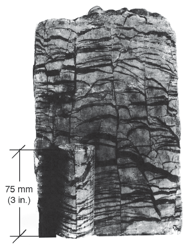
Segregation ice often forms regularly spaced layers as shown in Figure 2. As each layer forms, it tends to suck the soil beneath it dry. When the force of cryosuction is no longer able to lift water from below, thickening of the current layer ceases, and cooling proceeds downward until a new ice layer can begin to form at a greater depth.
It is important to understand that ice segregation (and hence soil heaving) requires the presence of three components: frost-susceptible soils, water, and freezing temperatures. Remove any one of these three, and frost heave does not occur.
Frost Susceptibility of Soils
The frost susceptibility of a soil is largely a function of the amount and relative size of smaller soil particles. Smaller particles fill spaces between larger particles, thus reducing the effective size of soil pores. The smaller the effective pore size, the greater the capillary action within the soil.
In the Canadian Foundation Engineering Manual, soil scientist Arthur Casagrande reports that “under natural conditions and with sufficient water supply, expect considerable ice segregation in uniform soils containing more than 3% of grains smaller than 0.008 inches and in very uniform soils containing more than 10% smaller than 0.0008 inches. No ice segregation was observed in soil containing less than 1% of grains smaller than 0.0008 inches, even if the groundwater was as high as the frost line.” The manual also states that “the borderline between soils that are frost-susceptible and those that are not is not distinct, and those which appear to fall just clear of the Casagrande criteria should be treated with caution.”
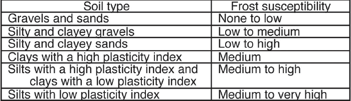
Table 1 lists the frost susceptibility of soils. To relate soil types in the table to Casagrande’s limits, note that clay-sized particles are defined as those less than 0.00008 inches, silt-sized particles as those between 0.00008 and 0.003 inches, and sand-sized particles as those between 0.003 and 0.08 inches. As a point of reference, particles less than 0.003 inches in diameter (silts and clays) cannot be distinguished with the naked eye.
Table 1 shows that frost heave is a non-issue when one is building on sands and gravels that do not contain silts and clays. As silt content increases, frost heave becomes more problematic. The most frost-susceptible soils are silts with a low plasticity index (PI). The PI indicates the breadth of the range of soil moisture content values for which a soil exhibits plastic properties. Soils with a high PI tend to have more clay-sized particles and clay-type minerals. On the basis of the previous discussion, one may conclude that soils with a higher PI are more susceptible to frost heave. This is true to a point. As the clay content of a soil increases, a point is reached where the clay content is so high, and effective pore size so small, that water is essentially blocked from moving through the pores. This is why a pure clay soil (i.e., a soil with a very high PI) is not as susceptible to frost heave as a pure silt soil (i.e., a soil with a lower PI).
Frost Penetration Depth
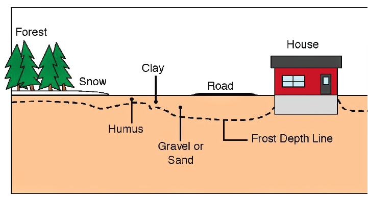
Frost heave is a problem only if the soil under a foundation freezes. To what extent frost penetrates a soil depends on soil type and cover (Figure 3) and on the temperature and duration of the winter weather.

The best measure of overall coldness and duration of winter weather is the air freeze index (AFI). This predictor of frost penetration depth is determined from cumulative freezing degree days. One freezing degree day accumulates for each degree the average daily temperature is below 32°F, with the average daily temperature taken as the average of the minimum and maximum daily temperatures. Table 2 shows how freezing degree days would accumulate for a 7-day period.
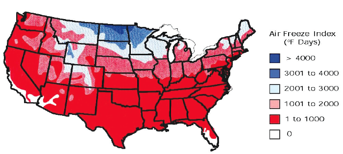
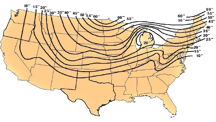
The AFI for a given winter is the largest difference between the maximum freezing degree day cumulative total reached at the start of the winter season and the minimum total reached during the same winter. Figure 4 contains a map of the AFI100 values for the contiguous United States. AFI100 values are AFI values with a mean reoccurrence interval of 100 years. In Alaska, AFI100 values range from a low of 1,000 °F•days to a high of 12,000 °F•days!
Average annual frost penetration depths for the contiguous United States are shown in Figure 5. Because frost frequently penetrates depths greater than the average annual depth, foundations on frost-susceptible soils should always be placed at depths greater than those in Figure 5 unless other steps are taken to keep the soil below the foundation dry or from freezing.
Frost Heave of Shallow Foundations
With respect to frost heave, a shallow foundation is defined as any foundation whose base is not located below frost penetration depth. According to this definition, the embedded post-foundations used to support many buildings would not be classified as shallow foundations because they are purposely designed and installed with their base below frost penetration depth.
A concrete slab-on-grade floor placed inside a building with embedded posts should be treated as a shallow foundation. When overlying frost-susceptible soils, this slab may be subjected to frost heave unless the soil is kept relatively dry or is prevented from freezing. Frost heave in this case results in differential movement between the slab and embedded posts and can result in structural damage. Heaving will tend to be more uneven in a heated building because heat loss through the slab is more likely to keep soil under interior portions of the slab from freezing, while soil under slab edges freezes and heaves. It is not uncommon for such action to result in the formation of a crack in the slab that runs parallel to an exterior wall. This same differential slab movement and associated cracking are also a concern in buildings with posts mounted on the slab.
In general, if moisture in frost-susceptible soils underlying a slab is allowed to freeze, the slab would need be engineered with a proper amount of steel reinforcing to enable the slab to span, without failure, from high point to high point on the swollen soil surface. However, because no quick or accurate method currently exists for predicting variations in the location and magnitude of frost heave under a slab, designing a slab to float on frozen soil is really not an option available to the designer.
Another reason for not allowing soil under a slab to freeze is that frozen soil becomes extremely weak as it thaws. In fact, soil left saturated by melting water is generally measurably weaker than it was in its prefreeze state. This reduction in soil strength is referred to as thaw-weakening. It is a major problem with clay and silt-type soils and is largely responsible for the formation of potholes in asphalt pavements.
Documents containing procedures for sizing concrete slab-on-grade floors include these: American Concrete Institute (ACI) 360R-06 Design of Concrete Slabs on Ground, the U.S. Department of Defense’s Unified Facilities Criteria (UFC) 3-320-06A Concrete Floor Slabs on Grade Subjected to Heavy Loads (available for free download at https://www.wbdg.org/FFC/DOD/UFC/ufc_3_320_06a_2005.pdf), Concrete Floors on Ground, written by J. A. Farny and S. M. Tarr and published by the Portland Cement Association (PCA), and Design of Post-Tensioned Slabs-on-Ground, published by the Post-Tensioning Institute (PTI). Although none of these documents contains methodology for predicting the effects of frost heave, the PTI document contains procedures for determining differential slab heave due to moisture content changes in expansive and compressible soils.
Methods For Minimizing Frost Heave Under Shallow Foundations
To minimize frost heave potential, a designer has two primary options: Place the foundation on well-drained soils that are not susceptible to frost heave, or prevent soil under the foundation from freezing.
Building on well-drained soils that are not frost heave susceptible is the most common method used to minimize frost heave. This option frequently involves replacing any frost-susceptible soils located within 1 or 2 feet of grade with sands and gravels. The depth to which such soil replacement is needed depends primarily on frost penetration depth and on the quantity of heat lost from the building to the soil.
It is always beneficial to construct the subgrade so that the soil underlying the foundation stays relatively dry. Not only is this important for minimization of frost heave, it is also important for maintaining soil bearing capacity, maximizing soil thermal resistance, minimizing liquid and vapor diffusion into a building, and extending the durability of building components in soil contact.
The extent to which the soil underlying a foundation can be kept dry depends on such factors as foundation elevation relative to the surrounding terrain, soil type, distance to the ground water table, and type of perimeter drainage system (if employed). With respect to soil type, coarse-grained soils (i.e., sands and gravels) are much preferred because they drain quickly and are associated with minimal capillary action. As a rough approximation, capillary rise is 3 inches in a fine gravel, 6 inches in a coarse sand, 10 inches in a medium sand, 20 inches in a fine sand, 40 inches in a silt, and 80 inches in a clay. As previously noted, capillary action for a particular soil is largely a function of the amount and relative size of the smaller particles in the soil as they dictate capillary size. Thus, a soil that is 80% sand and 20% clay is likely to have a capillary rise approaching that of a pure clay soil.
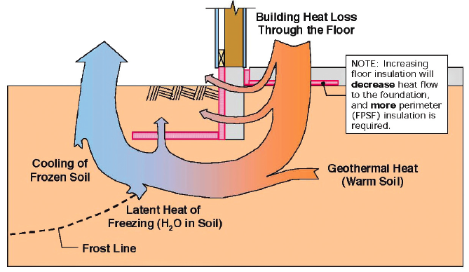
The second option for control of frost heave is to prevent freezing of soils located under the slab with a strategic use of insulation as shown in Figure 6. This insulation keeps building-heat energy and/or heat energy stored in deep underlying soil from being rapidly lost to cool winter air. When properly sized and placed, the insulation keeps all soil located immediately below even the shallowest of foundations from freezing. Shallow foundations that feature such insulation systems are commonly referred to as frost-protected shallow foundations (FPSFs).
SEI/ASCE 32-01
Procedures for sizing and locating FPSF insulation are contained in SEI/ASCE 32-01 Design and Construction of Frost-Protected Shallow Foundations. SEI/ASCE 32-01 is actually a slightly modified version of a National Association of Home Builders Research Center (NAHB RC) document published in 1994. The NAHB RC document was based on Scandinavian codes in existence since the 1960s; since the early 1950s, more than 1.5 million homes have been built with FPSFs in Sweden alone. NAHB RC prescriptive requirements for FPSFs appeared in the original version of the International Residential Code published in 2000. SEI/ASCE 32-01 was published in 2001 (as the -01 indicates).
The manner in which FPSF insulation is installed depends on the thermal classification of the building. SEI/ASCE 32-01 defines three building types: heated, unheated, and semiheated. A heated building is one with a minimum average monthly indoor temperature greater than 63°F. An unheated building is one with a minimum average monthly indoor temperature less than 41°F. Buildings falling between these two extremes are defined as semiheated.
Slab-on-grade floors of heated buildings are protected from frost heave by using the insulation systems shown in Figures 1a and 1b. Although systems with insulation located under the slab (Figures 1c and 1d) prevent building heat loss, it may not prevent soil located directly under the slab from freezing at locations near the building perimeter.
Simplified FPSF Design Method for Heated Buildings
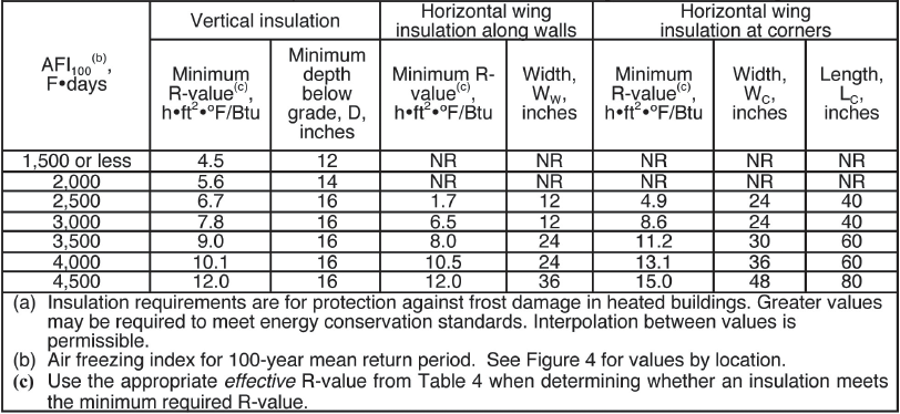
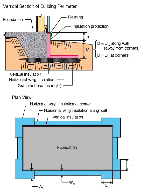
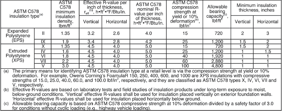
SEI/ASCE 32-01 contains both a simplified and a detailed method for determining insulation requirements for heated buildings. The simplified FPSF design method is a prescriptive specification requiring insulation in accordance with Table 3. This table contains R-values and dimensions for exterior vertical insulation and exterior horizontal wing insulation. Dimensions used in Table 3 are graphically defined in Figure 7. Table 4 contains effective insulation R-values to be used when one is determining whether insulation meets the required minimum R-value specified in Table 3. The simplified design method cannot be used when there is insulation underlying the slab with an R-value greater than 10 h•ft2•°F/Btu.
Detailed FPSF Design Method for Heated Buildings
In reality, there are an infinite number of combinations of insulation dimensions and R-values for both vertical and horizontal wing insulation that can be used to protect a heated building from frost heave. The SEI/ASCE 32-01 detailed FPSF design method is a performance specification that provides the designer with the flexibility to select the combination of insulation R-values and dimensions that work best for the job. In addition, the detailed method enables the designer to account for effects of insulation placed directly under a slab-on-grade floor. As noted in Figure 6, such insulation will decrease heat flow to the foundation, thereby requiring more perimeter insulation.


The detailed FPSF design method consists of the following steps:
Step 1: Determine the site’s design AFI. Approximate the AFI from Figure 4 or obtain a more site-specific value from the National Climatic Data Center FPSF website (https://www.ncdc.noaa.gov/climate-information/statistical-weather-and-climate-information/frost-protected-shallow-foundations).
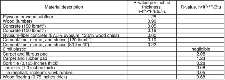
Step 2: Calculate the R-value for the floor slab, RF. Consider all insulating materials in the cross-section, including any floor covering. Table 5 contains R-values for selected materials. When determining RF, use dry-condition R-values for all materials including insulation. If RF varies over the slab area, calculate RF as the average over the perimeter (i.e., outer) 3 feet of the floor. If RF exceeds 28 h•ft2•°F/Btu, the designer must follow guidelines in the following section for an unheated building, because heat from the building is substantially blocked from moving into the ground and protecting the foundation.
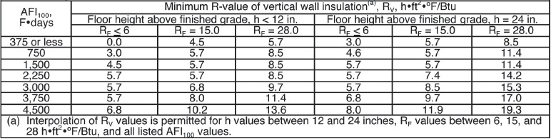
Step 3: Use Table 6 and the information from Steps 1 and 2 to determine the required R-value of the vertical insulation, RV.
Step 4: Based on the required RV from Step 3, select an adequate thickness of insulation using the effective R-values, reff, listed in Table 4. Individual panel thickness shall not be less than the minimum insulation thicknesses listed in the right columns of Table 4. Vertical insulation must extend from a depth D to the exterior, above-grade wall without exposing the foundation wall or other thermally conductive materials, as shown in Figure 7.
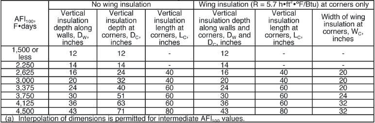
Step 5: Use Table 7 to select insulation dimensions for situations in which no wing insulation is desired, or where wing insulation is desired at corners only. Note that this wing insulation must have an R-value of 5.7 h•ft2•°F/Btu. Alternatively, use Tables 8 and 9 to determine wing insulation dimensions and R-values for applications where the depth D of all vertical insulation (i.e., that along the wall and at corners) will be fixed at 16 inches.
Step 6: Select an adequate thickness for required wing insulation by dividing the required minimum R-value of the insulation by its effective horizontal R-values, reff, listed in Table 4.
FPSF Design Method for Unheated Buildings
Geothermal energy is solely relied upon to keep frost-susceptible soils beneath the foundation of unheated buildings from freezing. As Figure 8 shows, this energy is prevented from rapidly leaving the soil by a continuous layer of insulation placed under the entire foundation. A non-frost-susceptible soil layer at least 6 inches thick must be placed below the insulation, or a non-frost-susceptible soil layer at least 12 inches thick must be placed above the insulation. The ground insulation layer and the non-frost-susceptible layer are additive to the minimum footing depth of 12 inches shown in Figure 8. Outside the foundation perimeter, the insulation must have a soil cover at least 10 inches thick.
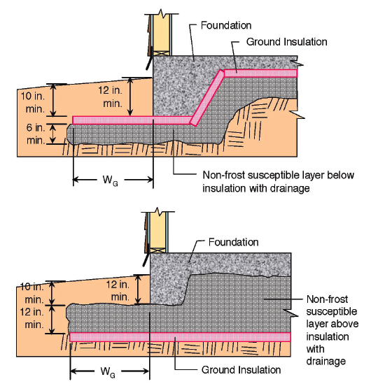
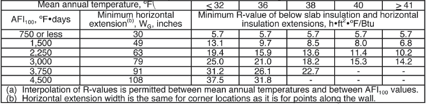
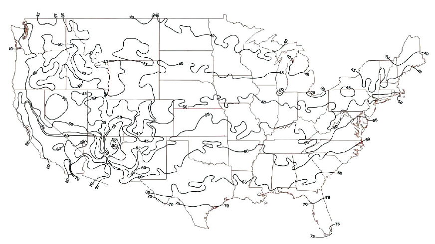
The distance WG that the ground insulation is required to extend past the perimeter of the building and the R-value of the insulation are obtained from Table 10. These values are dependent on AFI100 values as well as the mean annual temperature for the building site. See Figure 9 for mean annual temperatures.
R-values from Table 10 may be reduced by 0.3 h•ft2•°F/Btu for every 1 inch that the non-frost-susceptible layer thickness is increased beyond the required minimum. In addition, the R-value can be reduced by 0.3 h•ft2•°F/Btu for every 1-inch increase in soil cover thickness above the 10-inch minimum. Finally, WG may be reduced by 1.25 inches for every 1 inch that the insulation is buried beyond the 10-inch minimum cover.
FPSF Design Method for Semi-heated Buildings
The foundation of buildings classified as semi-heated shall be designed in accordance with the detailed FPSF design method for heated buildings, but with the minimum vertical insulation depth increased by 8 inches for both wall and corner areas of the semi-heated building.
Summary
Two good options exist for minimizing frost heave of shallow foundations in cold climates. First, the foundation can be located on soils not susceptible to frost heave. In this case, not all soils below a foundation need to be non-frost-susceptible, only those located above the frost penetration depth. The second option is to install insulation that prevents soil underlying the slab from freezing. Data and procedures presented in this article can be used to size these insulation systems. In heated buildings, this insulation is located around the outside of the foundation. In unheated buildings, it is located directly under the entire foundation.