Originally Published as: Concrete piers: Making post-frame buildings greener
FLASHBACK JANUARY 2006
Two decades have passed since this article first appeared in Frame Building News, yet the questions it addresses are more relevant than ever. Post-frame construction has continued to evolve, and builders today still face many of the same considerations surrounding durability, material availability, environmental impact, and long-term performance. Rising concerns about treated-wood preservatives, increasing interest in resilient foundation systems, and a growing focus on sustainability all make this a perfect moment to revisit the insights originally presented.
What readers will find in the article below is a clear and practical explanation of why concrete piers remain an important option in modern post-frame design. The advantages discussed speak directly to challenges builders continue to navigate. Whether you’re comparing foundation systems for cost, performance, or ease of construction, this reprinted article offers a thorough, engineering-based look at concrete piers that still applies to the projects you’re building today.
In short, this is a reminder that some foundational principles—literally—stand the test of time.
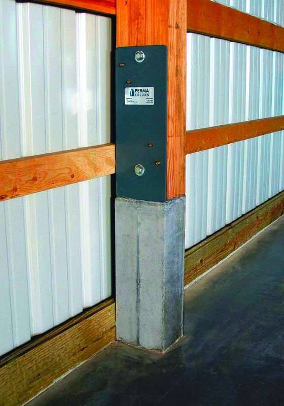
In recent years, there has been increased interest in constructing post-frame buildings that feature wood posts attached to embedded concrete piers. This interest has been largely spurred by the marketing and fabrication of buildings featuring concrete piers sold under the trade name of Perma-Column (figure 1). Although Perma-Columns are precast products, concrete piers also can be cast-in-place as was done during the 2001 construction of the post-frame building we used to conduct diaphragm action studies in Lester Prairie, Minn. (figure 2).
While slightly more costly than embedded wood post foundations, concrete piers offer many advantages over embedded wood posts and slab-on-grade foundations that builders may not have considered. After reading the following information on concrete piers and the sidebar that follows, it will be apparent that use of concrete piers decreases the environmental impact of post-frame buildings, thus making a green building system even greener.
Advantage of concrete piers over embedded wood posts
When it comes to concrete piers, the question foremost in a builder’s mind is why substitute concrete for a preservative-treated wood post when it is generally more difficult and costly to transport and install concrete components, and to attach other components to concrete? In answer to this question, I offer the following seven, largely-interrelated reasons.
1. Durability. Many end users have more confidence in the long-term durability of a concrete foundation than they do in a preservative-treated wood foundation. This is largely due to the poor performance of many solid-sawn posts that were not adequately preservative-treated for ground contact. It is important to note that to date, I am unaware of any documented failures of mechanically-laminated wood posts that have been properly CCA-treated for ground contact.
2. Reduced availability and/or higher cost of CCA-treated lumber. CCA is composed of the oxides of chromium, copper, and arsenic. Stating that arsenic is a known human carcinogen and that it is in the public’s best interest to reduce levels of potential exposure to arsenic, the Environmental Protection Agency banned manufacturers from treating wood with CCA for most residential uses effective December 31, 2003 (EPA, 2005). While posts for agricultural and commercial buildings can still be CCA-treated, the partial ban on CCA significantly reduces the amount of wood that is CCA-treated, making it more difficult and expensive to obtain.
3. Corrosiveness of CCA alternatives. Alternative treatments to CCA include Alkaline Copper Quat and Copper Azole. Like CCA, these alternative treatments rely on copper toxicity for effective protection from decay organisms. Unlike CCA, they are not time-tested and tend to leach more copper (Lebow, 2004; Townsend et al., 2003). The greater availability of dissolved copper in these alternative treatments results in increased galvanic corrosion when metals less noble than copper (e.g., magnesium, zinc, iron, steel, aluminum) are driven into or brought into direct surface contact with the treated wood.
4. Reduced use of preservative-treated lumber. Where possible, engineers try to eliminate preservative-treated lumber because it costs more than non-treated lumber, it generally requires use of more expensive, less-corrosive fasteners, and preservative wood treatments are pesticides which can make eventual disposal of preservative-treated wood problematic (Wilson, 1997). The cost of preservative treatment alone will drive engineers to use posts featuring treated wood spliced to untreated wood in an effort to save money for posts not requiring above ground treatment. Use of concrete piers in this situation eliminates the treated wood altogether, as well as the additional assembly costs associated with joining treated to untreated dimension lumber.
5. Lumber length. Lumber becomes increasingly expensive (on a board foot basis) in longer lengths. Additionally, dimension lumber is not readily available in lengths longer than 20 feet. When concrete piers are used, the overall length of the wood post is generally shortened by 4 to 7 feet. This means engineers are using shorter, less expensive lumber to obtain the same building heights, and also can build structures with 20-foot eave heights using unspliced sidewall posts.
6. Ease of building disassembly. Agricultural and commercial buildings have a relatively short functional design life. It is therefore beneficial to be able to easily disassemble building components for use in a more functional structure. This is much easier to accomplish when wood posts are attached to concrete piers.
7. Recycling. Reuse of lumber treated with a particular preservative is largely dictated by restrictions placed on its use after it has been on the market for several years. For example, it is not possible to reuse lumber treated with pentachlorophenol in buildings because of restrictions placed on its use in 1984. Some researchers have suggested that the development of good organic-based preservative wood treatments may result in restricted use of all heavy-metal based preservatives, making products treated with CCA, ACQ, and ACC of little value in the future. If this is the case, anything that can be done to replace preservative-treated wood with untreated wood may increase future value of a building.
Advantage of concrete piers over slab-on-grade foundations
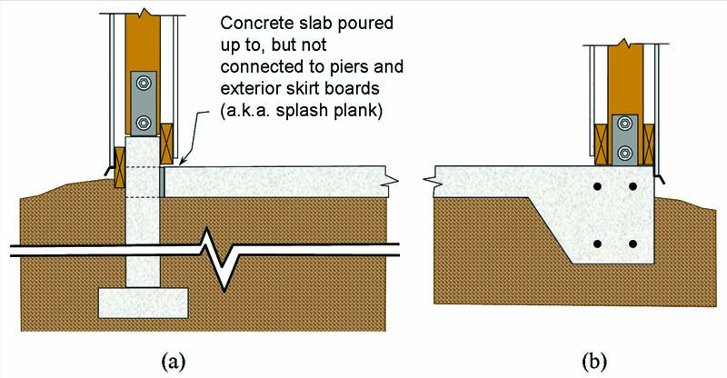
When an owner requests a post-frame building with a concrete floor, the builder generally has two options: erect the building with an embedded post/pier foundation system and then install the concrete floor as shown in figure 3a, or place the concrete floor first and then attach the wood posts to the concrete surface. When posts are placed on top of the slab, the slab edge must be thickened and reinforced with steel to handle transfer of post loads and to facilitate post attachment (figure 3b). Since this thickened and reinforced edge functions like a beam in distributing loads to the soil, it is referred to as a grade beam, and the entire slab becomes a slab-on-grade foundation.
When selecting between concrete pier and slab-on-grade foundation systems, the following four advantages of concrete piers should be considered.
1. Total concrete cost. Based on typical grade beam and pier dimensions, the amount of concrete required to add a grade beam around a slab will generally exceed the total amount required for concrete piers. This is especially true with larger post spacings (e.g., 8, 10, and 12 feet) which translate into fewer building piers and less required concrete.
2. Construction flexibility. With concrete piers, the interior slab is placed after the building shell has been erected. This has two major advantages. First, concrete is much more likely to be protected during placement from wind, precipitation in all forms, and temperature extremes. This can translate into fewer unexpected scheduling delays, less need for costly heat and moisture protection systems, and enhanced concrete surface finish, durability, and strength properties. Second, less preplanning is required for below slab installation of HVAC, plumbing and electrical system components. In fact, no preplanning is required when the interior concrete slab is placed after HVAC, plumbing and electrical system installations have been completed.
3. Structural integrity. The probability of a foundation failure on an expansive clay soil is greatest for a stiffened slab-on-grade (a slab with a reinforced perimeter grade beam) and least for a building completely supported on piers (Green, 2005). Likewise, a building supported on concrete piers is much less likely to be plagued with frost heave problems than is a stiffened slab-on-grade.
4. Foundation reuse. Using a rather simple tripod and hydraulic cylinder, concrete piers can be withdrawn from the soil and reused in another building at a completely different location. Practically speaking, the only way to reuse a grade beam foundation is to rebuild on top of it.
Concrete pier design
Concrete pier design begins with a structural analysis that provides the shear force, axial force, and bending moment at the top of the piers. These forces are largely influenced by the bending (i.e., rotational) stiffness of the concrete pier-to-wood post connection. Most steel brackets used by the post-frame industry to attach wood posts to cast-in-place concrete are treated as pin connections in design because of the lack of bending stiffness of the steel bracket-to-concrete connection, the steel bracket-to-wood post connection, and/or the steel bracket itself. When concrete-to-wood post connections lack bending stiffness, the building designer must rely upon diaphragm action and/or on rigid column-to-truss connections to help handle horizontal components of applied structural loads. Note that the concrete pier-to-wood post connections of the Lester Prairie test building (figure 2) were purposely designed to behave as pins so that diaphragm action could be more effectively evaluated.
Once design loads for a concrete pier have been determined, the pier cross-sectional dimensions and the amount and location of steel reinforcing can be determined in accordance with ACI 318 Building Code Requirements for Structural Concrete (ACI, 2005). Calculation of embedment depth can be done in accordance with ANSI/ASABE Engineering Practice (EP) 486.1 Shallow Post Foundation Design (ASABE, 2005). Although the EP was largely developed for embedded wood posts, the practice also applies to other embedded post materials. EP Section 3.1.1, which defines “post,” specifically states that “Posts include members of any material with assigned structural properties such as solid or laminated wood, steel, or concrete.” The fact that the EP applies to concrete piers makes sense since soil will not react differently to posts/piers of similar shape, size and flexural stiffness.
Cast-in-place concrete piers
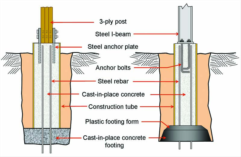
Examples of cast-in-place concrete piers are shown in figures 4a and 4b. These figures show respectively, a concrete pier poured separately of, and simultaneously with, a concrete footing.
Cast-in-place piers are typically formed with single-use, spirally-wound paper tubes. These forms are frequently referred to as concrete forming tubes, concrete construction tubes, or by a manufacturer’s trademarked name (Sonotube, Smurfit, Essex Tubes, Formatube, Opt-T-Tube, Quiktube, Crescent Tube). Tubes up to 4 feet in diameter and 20 feet long are available. Nominally 8- and 12-inch diameter tubes are generally stocked locally and retail for approximately $1.50/foot and $2/foot, respectively. Note that several tubes are nested for shipping (i.e., tubes are slid inside other tubes), and thus are available in a variety of diameters close to the nominal size.
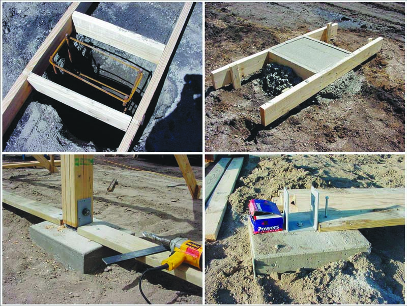
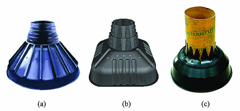
Simultaneously pouring piers and footings saves considerable time and is facilitated with special isolated footing forms. Three companies currently manufacture and market such forms as shown in Figure 5. The first patented was TubeBase produced by Sound Footings LLC which is owned by DEW Construction Corp. of Williston, Vermont (Wells, 1987). Ten years later the Bigfoot Systems Footing Form produced by F&S Manufacturing Inc., Martins Point, Nova Scotia (Swinimer, 1998) and the Redibase Forming System by Redibase Inc., Fulford, Quebec (Croghan, 1998) were patented. Suggested retail prices for a 24-inch TubeBase, Bigfoot Systems Footing Form, and Redibase Forming System are $18, $21, and $11, respectively. Construction tubes are attached to the Redibase Forming System with duct tape, and to the TubeBase and Bigfoot Systems Footing Forms with screws.
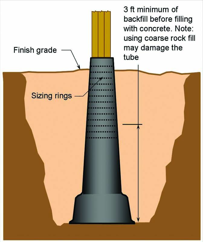
Figure 6 shows another forming system for cast-in-place piers — the one-piece Footing Tube patented and sold by Brent Cliff of Fredericton, New Brunswick (Cliff, 2001). Three different Footing Tube sizes are available: a 6-inch deck tube, an 8-inch footing tube, and a 10/12-inch footing tube. The 6-inch deck tube has an overall length of 54 inches, top diameter of 6 inches, and inside base diameter of 14 inches. The 8-inch footing tube is 62 inches long with an 8-inch top diameter and 22-inch inside base diameter. The 10/12-inch footing tube has a 2-inch top ring that is 10 inches in diameter. When this top ring is cut off, the remaining tube is 62 inches long with a 12-inch top diameter and 22-inch inside base diameter. The 6-inch deck and 8- and 10/12-inch footing tubes hold 2.3 feet3, 4.8 feet3 and 8.5 feet3 of concrete, respectively, and have a manufacturer’s suggested retail price of $35, $41.50, and $46, respectively.
A cast-in-place alternative to the piers shown in figures 4 and 6 is to auger a hole equal in width to the required footing diameter, and then fill it with concrete. Although this eliminates much of the formwork, the resulting soil-concrete interface makes it more susceptible to frost heave, and such piers can end up costing more than systems featuring special forms. For example, at $80 per cubic yard, total concrete cost is around $47 for a 5-foot long pier that is poured into a hole with an effective average diameter of 24 inches (see Table 1). Replacing this with a system utilizing a 12-inch diameter construction tube and 24-inch diameter Redibase Forming System (the base holds 1.65 feet3 of concrete) cost slightly less than $34. The cost advantage of using footing forms (over pouring directly into an augered hole) increases with increases in hole depth, required footing diameter and/or concrete cost.
There are many different ways to attach a post/column to a concrete pier. One option for wood posts is to attach them to steel bars cast vertically in the pier (figure 4a). A more conventional option is to rely on anchor bolts cast in the concrete (figure 4b) or drilled into the concrete (figure 2). Alternatively, a steel column can be welded to a horizontal steel plate that has been cast into the top of the pier.
Precast concrete piers
A precast concrete pier is any pier that has been cast in a location other than its final location. Consequently, a pier fabricated on-site would be considered a precast pier if it is moved into a posthole after significant curing has taken place.
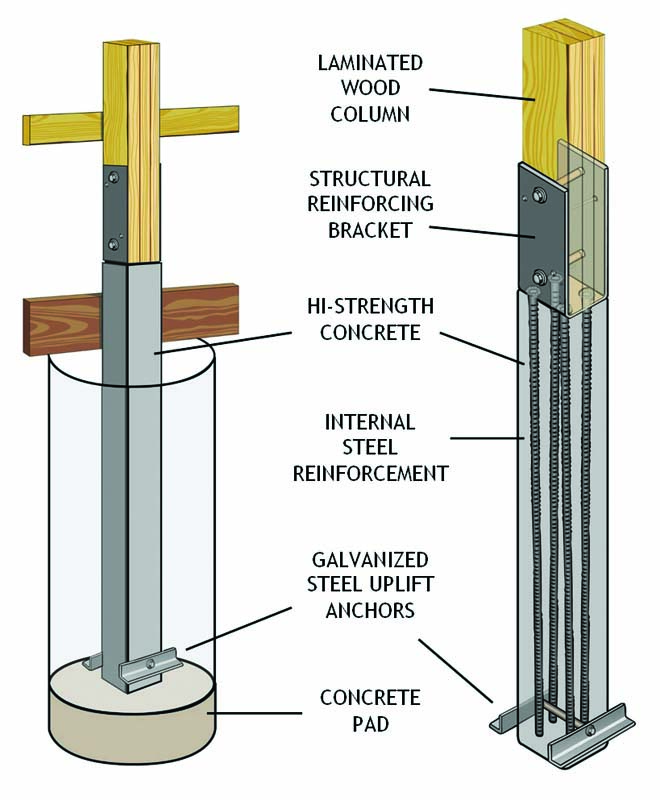
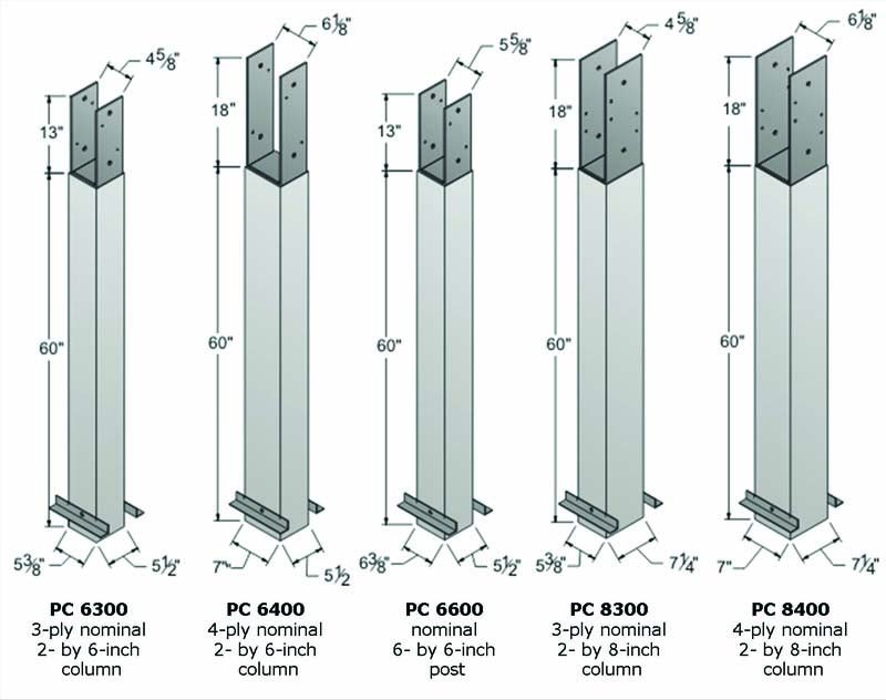
As previously noted, recent interest in concrete piers is largely due to construction of numerous post-frame buildings with Perma-Columns (figure 1) — a rectangular precast concrete pier developed and patented by Perma Column Inc. of Ossian, Ind. (Meyer and Stoller, 2005). The schematic in figure 7 shows the four continuous steel reinforcing bars which are part of every Perma-Column. Figure 8 shows the five different sized piers the company currently produces at each of its four U.S. manufacturing locations. Typical pricing for the PC6300, PC6400, PC8300, and PC8400 are $59, $68, $85, and $89, respectively. Note that Perma-Columns are a little bit wider but equal in width to the wood post/column they support. Engineering design properties for the concrete base and steel connector are available from www.permacolumn.com.
Precast vs. cast-in-place
Precasting of piers would appear to have the following advantages over casting piers in-place.
1. Concrete quality. Precasting is almost always done in a dedicated batching plant where it is easier to control concrete ingredients and the conditions under which the ingredients are mixed and then consolidated into forms. Placement of reinforcing is also more easily monitored in a plant setting, and concrete can be ideally cured in special humidified chambers.
2. Handling fresh concrete. Precasting eliminates handling of ready-mix concrete on the jobsite. This eliminates the need for concrete placement tools and the water needed to clean them. It should be noted that concrete pier placement requires few tools (and hence cleaning water) if the concrete ready-mix delivery truck can directly place concrete in all formwork.
3. Construction delays. Workers must wait for cast-in-place concrete piers to cure before proceeding with building shell assembly. Additionally, adverse weather conditions can delay concrete placement. On occasion, field personnel are left waiting for concrete delivery because they have finished their forming and other preparation work well before scheduled delivery and have nothing left to do, and/or the delivery is late.
4. Post preassembly. Irregardless of the type of pier used, the wood post/column must be attached to the pier at some point. In the case of precast piers, this attachment can be made before piers are inserted into post holes (i.e., the entire post can be preassembled). This results in a post installation that is essentially no different than that for an all-wood assembly. Manufacturers often opt to do this preassembly in the factory where adverse weather is never a factor and special fixtures can be utilized to obtain quick and accurate assembly.
5. On-site labor. Installation of cast-in-place piers requires that concrete forms and steel reinforcing be carefully installed and fixtured in place, and that elevation of pier tops be established prior to concrete placement. More difficult and time-consuming is the fixturing of any post/column anchors that are to be installed in the fresh concrete. For this reason, designers may opt to drill-in anchors after concrete has cured. Drilling-in anchors also takes time, and using them places more restrictions on design since it is very difficult to achieve much of a moment resisting connection with them.
Cast-in-place piers would appear to have the following advantages over precast piers.
1. Uniformity of contact. Cast-in-place concrete conforms to soil and whatever else it is cast against. This translates into good, uniform contact between soil and footing, and between footing and pier in situations where they are poured separately. Conversely, precast piers are typically used with precast footings, and good uniform contact between a precast footing and the soil requires that the soil surface be flat prior to footing placement. Additionally, if the precast footing is not level, the precast pier will only make line or point contact with the footing. Obtaining a flat and level surface for precast footing placement is much easier with the use of a posthole bottom leveler (Bohnhoff, 2005).
2. Height Adjustment. The top elevation of cast-in-place piers is controlled by striking off the surface to its desired height during concrete placement. The top elevation of a fixed-length precast pier can only be controlled by controlling footing elevation. The latter is not difficult, but adds slightly to the time required to place footings. During recent construction of a post-frame building, I used a posthole bottom leveler with an attached laser level receiver to level the bottom of postholes to a predetermined elevation. I then compacted the soil, installed the precast footings, and used the laser level to measure the installed depth of each footing. These measurements revealed a standard deviation on final elevation of only 0.35 inches.
The ultimate choice as to whether to use precast or cast-in-place concrete piers will typically come down to overall cost. There is typically less uncertainty in the pricing of precast pier systems since there are fewer unknowns relating to on-site installation. Each system requires the storage, handling and transportation to the jobsite of components (precast piers in one case; formwork, steel reinforcing, and anchors in the other). On-site labor is measurably greater for cast-in-place piers. Cost for site delivered concrete will depend on location and quantity needed. Note that the typical pier does not require that much concrete, and thus for smaller buildings you will generally be required to pay an additional delivery fee.
Conclusions
Although concrete piers may be more expensive than embedded wood post foundations, they have advantages over their embedded wood counterparts, and these advantages become increasingly important with time. Based on total cost, construction flexibility, structural integrity, and component reuse, a concrete pier foundation system with an isolated concrete slab would appear to be a better option than a slab-on-grade foundation system. Design of precast and cast-in-place concrete piers is a very straightforward process that can be accomplished using common engineering design specifications and procedures.
Construction of cast-in-place piers has been enhanced by the broad availability of round, cardboard forming tubes, and the manufacture of special isolated footing forms which attach directly to cardboard tubes. These isolated footing forms enable quick fabrication of a concrete post with a bell-shaped bottom for increased bearing capacity and uplift resistance. Precast piers have several advantages over cast-in-place concrete piers. It is important to account for these factors during any economic/feasibility analysis comparing the two systems.
References
- ACI. 2005. ACI 318-05: Building code requirements for structural concrete and commentary. American Concrete Institute, Farmington Hills, MI. (http://www.concrete.org/)
- ASABE. 2005. ANSI/ASAEEP486.1 Shallow post foundation design. In the 52nd edition of ASAE Standards. American Society of Agricultural and Biological Engineers. St. Joseph, Mich. (http://www.asabe.org/)
- Bohnhoff, D. R. 2005. Post Installation Tools. Presented at the 2005 ASAE Annual International Meeting, Tampa, FL. ASAE Paper No. 054119 ASABE, St Joseph, MI.
- Cliff, B. 2001. Anti-frost concrete mould. U.S. Patent 6,318,700. November 20, 2001. Available at: http://www.uspto.gov/patft/index.html.
- Croghan, M.T. 1998. Base mold for concrete post. U.S. Patent 5,800,727. September 1, 1998. Available at: http://www.uspto.gov/patft/index.html.
- Green, E.C. 2005. Excessive movement: Risk management and the design of foundations on expansive clay soil. Structural Engineer; October, 2005. pp. 34-37.
- Lebow, S. 1996. Leaching of wood preservative components and their mobility in the environment—Summary of pertinent literature. Gen. Tech. Rep. FPL–GTR–93. Madison, WI: U.S. Department of Agriculture, Forest Service, Forest Products Laboratory. 36 p.
- Lebow, S. 2004. Alternatives to chromated copper arsenate (CCA) for residential construction. In: Proceedings of Environmental Impacts of Preservative-Treated Wood February 8 – 11, 2004; Orlando, Florida, USA. Florida Center for Environmental Solutions Gainesville, Florida; (pre-conference Proceedings) 1 CD-Rom pp 1-12. Available at: http://www.fpl.fs.fed.us/documnts/pdf2004/fpl_2004_lebow002.pdf
- Meyer, R.L. and P.T. Stoller. 2005. Precast concrete column for use in post-frame construction. U.S. Patent 6,964,139. November 15, 2005. Available at: http://www.uspto.gov/patft/index.html.
- Swinimer K. 1998. Prefabricated form for molding a footing of a settable structural material. U.S. Patent 5,785,459. July 28, 1998. Available at: http://www.uspto.gov/patft/index.html.
- Townsend, T., K. Stook, M. Ward, and H. Solo-Gabriele. 2003. Leaching and toxicity of CCA-treated and alternative-treated wood products. Technical Report #02-4. Florida Center for Solid and Hazardous Waste Management, 2207 NW 13 Street, Suite D, Gainesville, FL 32609. 137 p.
- USEPA. 2005. Chromated Copper Arsenate (CCA): Health and Safety Information. Published on the U.S. Environmental Protection Agency website at: http://www.epa.gov/oppad001/reregistration/cca/health_safety.htm
- Wells, G.T. 1987. Footing form. U.S. Patent 4,673,157. June 16, 1987. Available at: http://www.uspto.gov/patft/index.html.
- Wilson, A. 1997. Disposal: The Achilles’ Heel of CCA-Treated Wood. Environmental Building News. Volume 6, Number 3, March 1997.