Guidance From the Pole Barn Guru
Sitting in a hotel room in Wilsonville, Oregon, on Christmas Day, I am reminding myself I have procrastinated about as long as possible on writing this article I have known about since August. Now it isn’t as if I have not written it a dozen times in my head, it is wanting to craft solutions both structurally sound, as well as practical (and cost effective) for installation.
Before we get too deep in over our heads, a brief disclaimer. I went to school to be an architect. I am not a Registered Professional Engineer and ultimately any calculations and/or recommendations should be reviewed by your engineer. Calculations provided here can be adapted to fit your lumber choices and/or column spacing by “plugging and playing.”
For the benefit of Frame Building News readers: My experience and expertise is in post-frame construction, as will be reflected by my recommendations. If you are not currently a post-frame builder, you may want to explore it further, if for no other reason to have one more design solution available in your arsenal.
Where to start?
Determining loads to be resisted.
2021 Building Codes (currently adopted in most jurisdictions) are based upon ASCE 7-16. Wall forces will depend upon where components are located on any given wall. Most often, they will fall within Zone 4. Zone 5 is at corners and is defined as being 10% of least horizontal dimension (length or width) or 0.4 x height, whichever is smaller, but not less than either 4% of least horizontal dimension or 3 feet.
Negative (suction) forces for components and cladding are greater than inward forces, so will govern. Forces increase with mean height of roof (not wall or eave height), for sake of discussion we will use 20 feet (reflected in Tables). We will also assume building is enclosed (this may limit openings and require wind rated doors). Most building sites are also wind Exposure C.
Entry door columns….seriously, did any of us (me included, until recent years) really give them much thought? My mentor from 45 years ago instructed me to plant a pressure treated 4×4 next to entry doors and call it good (of course, he also gave me mountains of other bad information).
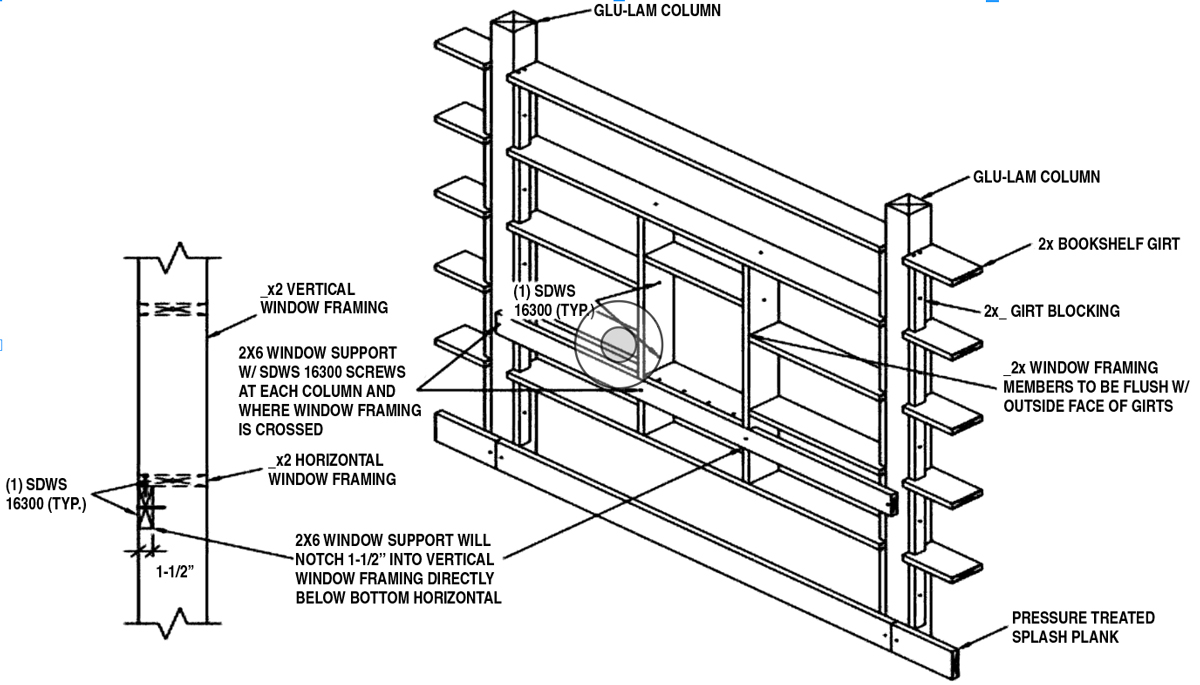
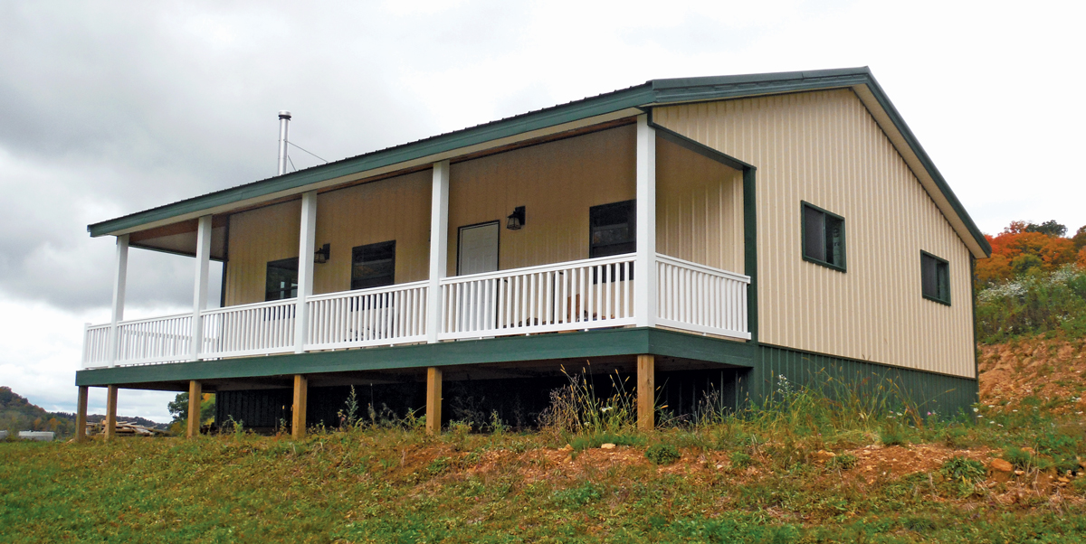
Photo courtesy Hansen Pole Buildings
Ever try to find a 4×4 or even a 4×6 pressure treated to UC-4B requirements? Good luck. Our design solution ended up being mounting a 4×6 #1 SYP to a Simpson Strong-Tie EPB46 bracket. Eliminated need for pressure treating. But does it work structurally?

(8 x Sm x Fb x Cd) / (Tributary area x Span^2) = Load carrying capacity in psf (pounds per square foot).
Sm = Section Modulus of member (Width x Depth^2 / 6) for a 4×6 = 17.646”
Fb = Fiberstress in Bending, for a 4×6 #1 SYP = 1350
Cd = Duration of Load, for wind = 1.6
Tributary area = worst case would be ½ of bay width between columns (using 12’ bay for this example)
Span = height of door
(8 x 17.646” x 1350 x 1.6) / ( 69.94” x 6.67’^2) = 98 psf, so appears load carrying capacity is all good.
But wait! Column has to meet deflection criteria.
IBC Table 1604.3 gives us deflection limitations. For exterior walls with flexible finishes (gypsum wallboard is a flexible interior finish), limitation is l/120. However we get further baffled with some sly footnotes. Footnote “a” allows us to use l/90 for secondary wall members supporting formed metal siding (would not apply if column supports gypsum wallboard on interior). Footnote “f” allows for wind load to be permitted to be taken as 0.42 times component and cladding loads.
What footnote “f” does not tell us is this 0.42 is of basic design wind speed V (used when calculating by LRDF). As most of us use Allowable Stress Design, this equates to 0.7 times Vasd values.
Allowable deflection will be 80” / 90 = 0.889”
Maximum actual load within deflection would be calculated by:
(384 x E x I) / (5 x tributary width in feet/12 x span in inches ^4 x allowable deflection)
E = Modulus of Elasticity = 1,600,000 for 4×6 #1 SYI = Width x Depth^3 / 12 = 48.526 for a 4×6
(384 x 1,600,000 x 48.526) / (5 x 5.803’/12” x 80”^4 x .889”) = 338.6 psf / 0.7 = 483.8 psf
4×6 #1 SYP appears to be more than a reasonable option (as would #2 DFir/DFL).
Now, what about supporting top end of column?
With 2×6 external girts, 24 inches on center (these may be slightly more conservative than what your engineer may arrive at):
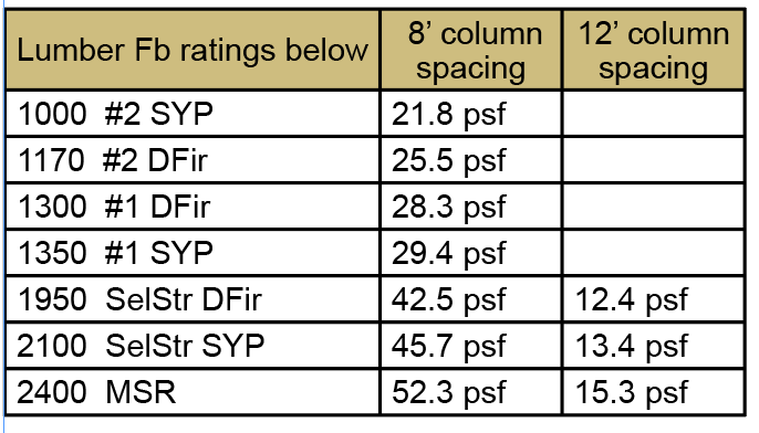
A better design solution (especially for 12 foot column spacing) would be to bookshelf this girt. We happen to use 2×6 2400msr, at 32 inches on center, good for roughly 38 psf.
How about windows?
For external girts, let us place a 4’x4’ window between 2×6 #2 SYP girts, where girt spacing (other than at window itself) is 24 inches on center and an 8 foot column spacing:
(8 x 2.0625 x 1000 x 1.6 x 1.15) / (36” x 8’^2) = 13.18 psf
Deflection changes when a window enters our scenario. IBC 1604.3.7 limits deflection to l/175 using 0.6 times Component and Cladding pressures (0.6 happens to be Vasd).
(384 x 1,600,000 x 1.547) / (5 x 3/12 x 96”^4 x 0.549”) = 16.31 psf
Although bending governs this scenario, load carrying capabilities are fairly small.
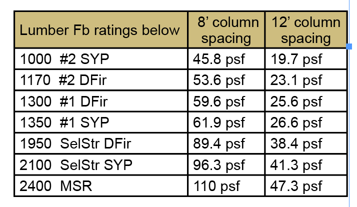
For higher wind loads or wider bay spacing, bookshelf wall girts provide a better design solution
In bending:
However deflection may control (so be sure to check both):
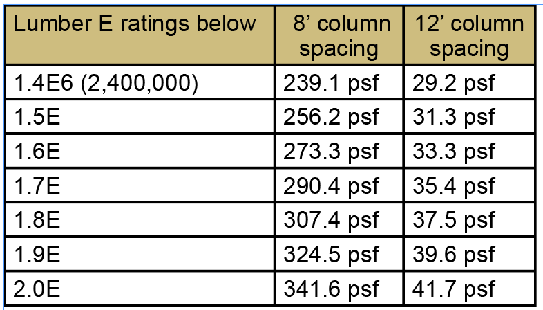
With bookshelf girts, an external girt should be placed beneath girt below window (forming an inverted “L”) to prevent undue downward deflection.